Do you have a question about the LG 32LN54 series and is the answer not in the manual?
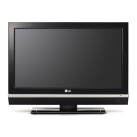
| Screen Size | 32 inches |
|---|---|
| Display Type | LCD |
| Backlight Type | LED |
| Refresh Rate | 60 Hz |
| HDMI Ports | 2 |
| USB Ports | 1 |
| Aspect Ratio | 16:9 |
| Resolution | 1366 x 768 |
| Speakers | 2 |
Provides general safety rules and guidance for servicing electronic equipment, emphasizing isolation transformers and proper handling.
Details the procedures for performing AC leakage current checks (cold and hot) to ensure user safety.
Outlines fundamental precautions for servicing, including unplugging power and handling components safely.
Provides instructions on preventing damage to sensitive electronic components from static electricity.
Details recommended techniques and tools for soldering electronic components.
Covers procedures for removing and replacing various components like ICs, transistors, diodes, and fuses.
Explains methods for repairing damaged copper patterns on printed circuit boards using jumper wires.
Defines the TV model application range and the conditions required for testing.
Outlines test methodologies and general specifications for market, broadcasting, and channel storage.
Details specifications for Component Video and HDMI inputs, including DTV and PC modes.
Covers the scope of adjustments, designation, and the main PCB check process.
Instructions for downloading software updates and boot files via USB or ISP utility.
Details the ADC calibration process and steps for checking TV functions like display and sound.
Guides through the total assembly line process and auto-control interface directions.
Covers CASE Cool adjustment, DDC EDID writing, and model option downloads.
Details outgoing condition configuration, GND, HI-POT testing, and EYE-Q function check.
Diagnoses issues related to the TV's power-up sequence and initial boot process.
Provides steps to troubleshoot problems with Digital/Analog TV, AV, and Component video signals.
Addresses troubleshooting steps for HDMI, MHL video, and all source audio issues.
Guides through troubleshooting audio problems for Digital/Analog, AV, and Component inputs.
Illustrates the main System-on-Chip (SOC) and its interconnected peripherals.
Shows the block diagram for side, rear, and tuner interface connections.
Provides a visual exploded view for identifying and locating TV components.
Details test points for CI slot, SCART, Headphone, and S2 on non-EU models.
Illustrates the power detection circuit and various voltage supply rails.
Shows the schematic diagram for the infrared receiver and LED control.
Details the schematic diagram for the side USB port.
Illustrates the detailed schematics for HDMI and MHL connections.
Shows the schematic diagram for the SPDIF optic output jack.
Details the pin assignments for LVDS connectors used in Non-EU models.
Illustrates the schematic for global tuner blocks, excluding EU and China.
Shows the wiring details for AV and Component input jacks.
Details the schematic diagram for the Ethernet port.
Provides the circuit diagram for the STA380BWEF audio amplifier IC.
Shows the schematic for the Mstar debug 4-pin connector.
Illustrates the schematic diagram for the RS-232C communication port.
Details schematics for NAND flash memory and the main SOC.
Details configuration options for model and memory settings.
Shows the schematic diagram for the RS-232C phone connector.
Illustrates the schematic for the DDR3 2GB Hynix memory module.
Details serial flash memory configurations for SPI boot (Non-OS).