- 10 -
LGE Internal Use OnlyCopyright © LG Electronics. Inc. All rights reserved.
Only for training and service purposes
* If downloading version is more high than your TV have, TV
can lost all channel data. In this case, you have to channel
recover. if all channel data is cleared, you didn’t have a DTV/
ATV test on production line.
* After downloading, have to adjust Tool Option again.
(1) Push "IN-START" key in service remote control.
(2) Select "Tool Option 1" and push "OK" key.
(3) Punch in the number. (Each model has their number)
3.1. ADC Process
(1) ADC
- Enter Service Mode by pushing "ADJ" key,
- Enter Internal ADC mode by pushing "►" key at "8. ADC
Calibration".
<Caution> Using "P-ONLY" key of the Adjustment remote
control, power on TV.
If there is no Component Input, disappear “ADC Comp” message.
* ADC Calibration Protocol (RS232)
Adjust Sequence
▪ aa 00 00 [Enter Adjust Mode]
▪ xb 00 40 [Component1 Input (480i)]
▪ ad 00 10 [Adjust 480i Comp1]
▪ xb 00 60 [RGB Input (1024*768)]
▪ ad 00 10 [Adjust 1024*768 RGB]
▪ aa 00 90 End Adjust mode
* Required equipment : Adjustment remote control.
3.2. Function Check
3.2.1. Check display and sound
■ Check Input and Signal items. (cf. work instructions)
1. TV
2. AV
3. COMPONENT (480i)
4. RGB (PC : 1024 x 768 @ 60hz)
5. HDMI
6. PC Audio In
* Display and Sound check is executed by Remote controller
Caution : Not to push the INSTOP key after completion if the
function inspection.
4. Total Assembly line process
4.1. Adjustment Preparation
▪ W/B Equipment condition
CA210
: CCFL/EEFL -> CH9, Test signal: Inner pattern(80IRE)
LED -> CH14, Test signal: Inner pattern(80IRE)
▪ Above 5 minutes H/run in the inner pattern. (“power on” key
of adjust remote control)
▪ Edge LED W/B Table in process of aging time (Only LGD
Edge LED Module except AUO, CMI, IPS Module)
CA210 : CH 14, Test signal : Inner pattern (80IRE)
Normal line
* Check the Table Data and the Spec after H/R
Aging chamber
* Check the Table Data and the Spec after H/R
NO Item CMD 1 CMD 2 Data 0
Enter Adjust
MODE
Adjust
‘Mode In’
A A 0 0
When transfer the ‘Mode In’,
Carry the command.
ADC adjust ADC Adjust A D 1 0
Automatically adjustment
(The use of a internal pattern)
Mode Temp Coordinate spec
Cool 13,000 K
X=0.270 (±0.002)
Y=0.271 (±0.002)
<Test Signal>
Inner pattern
(204gray,
80IRE)
Medium 9,300 K
X=0.285 (±0.002)
Y=0.293 (±0.002)
Warm 6,500 K
X=0.310 (±0.002)
Y=0.325 (±0.002)
GP4
Aging time
(Min)
Cool Medium Warm
X y x y x y
271 270 285 293 313 329
1 0-2 281 287 295 310 320 342
2 3-5 280 285 294 308 319 340
3 6-9 278 284 292 307 317 339
4 10-19 276 281 290 304 315 336
5 20-35 275 277 289 300 314 332
6 36-49 274 274 288 297 313 329
7 50-79 273 272 287 295 312 327
8 80-119 272 271 286 294 311 326
9 Over 120 271 270 285 293 310 325
GP4
Aging time
(Min)
Cool Medium Warm
X y x y x y
271 270 285 293 313 329
1 0-5 280 285 294 308 319 340
2 6-10 276 280 290 303 315 335
3 11-20 272 275 286 298 311 330
4 21-30 269 272 283 295 308 327
5 31-40 267 268 281 291 306 323
6 41-50 266 265 280 288 305 320
7 51-80 265 263 279 286 304 318
8 81-119 264 261 278 284 303 316
9 Over 120 264 260 278 283 303 315
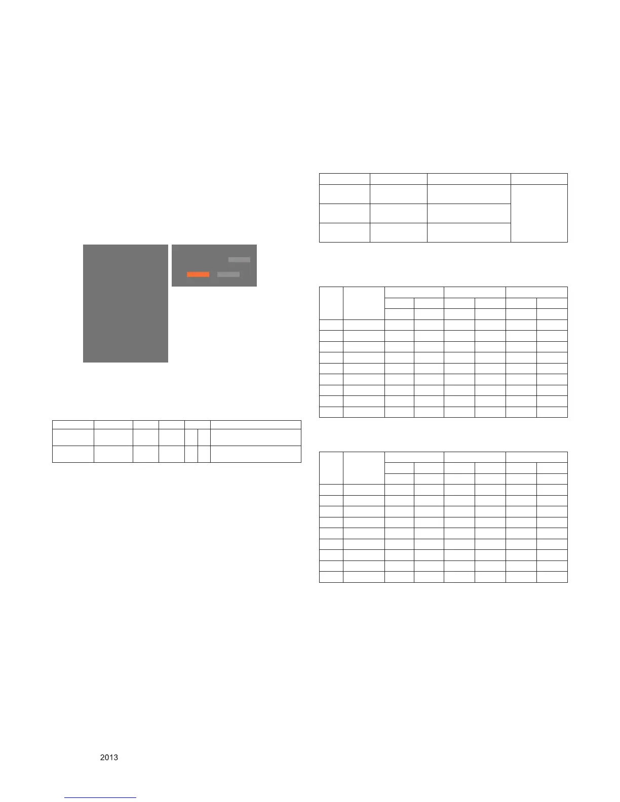
EZ ADJUST
0. Tool Option1
1. Tool Option2
2. Tool Option3
3. Tool Option4
4. Tool Option5
5. Tool Option6
6. Commercial Tool Option
7. Country Group
8. Area Option
9. ADC Calibration ►
10. White Balance
11. 10 Point WB
12. Test Pattern
13. EDID D/L
14. Sub B/C
15. Ext. Input Adjust
ADC Calibration
ADC RGB
Start
NG
Reset
 Loading...