ENGLISH
24
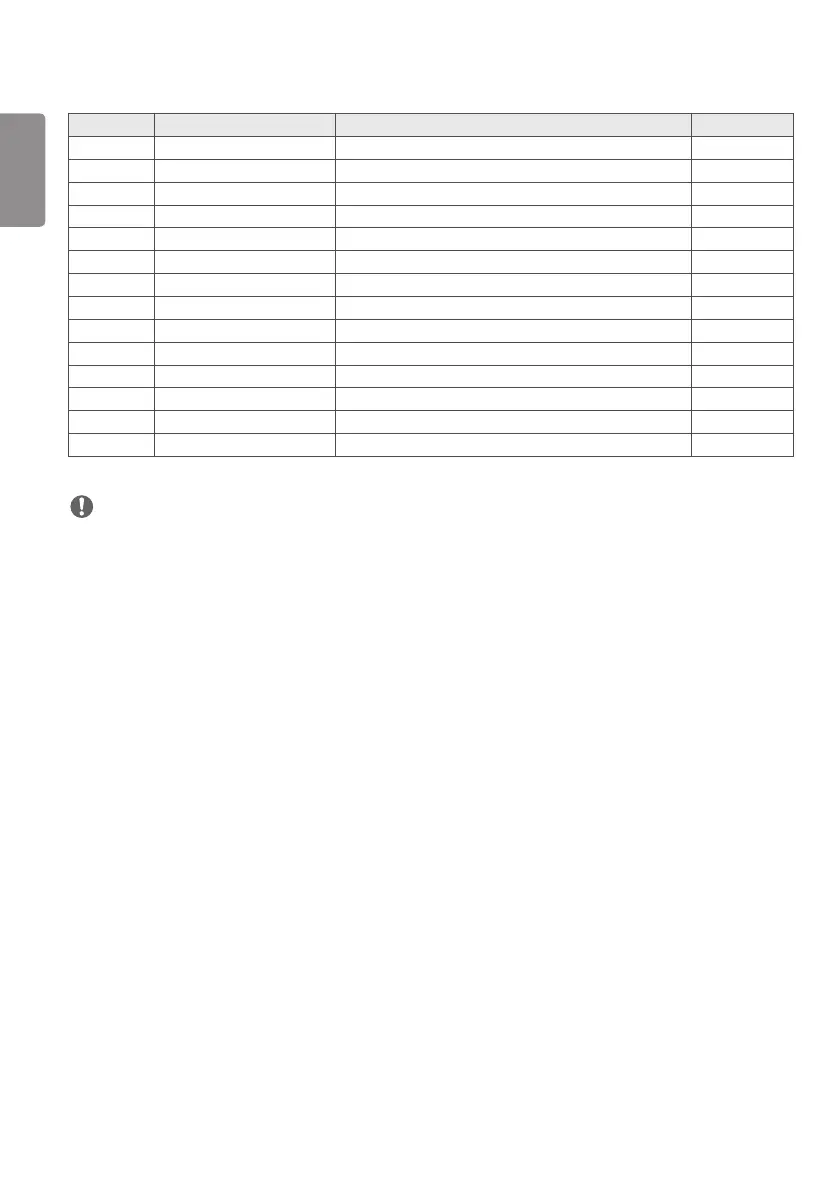
Pin No. Symbol Description Note
38 R2DN SECOND LVDS Receiver Signal(D-)
39 R2DP SECOND LVDS Receiver Signal(D+)
40 NC No Connection 4
41 NC No Connection 4
42 NC or GND
No Connection or Ground
43 NC or GND
No Connection or Ground
44 GND Ground 5
45 GND Ground
46 GND Ground
47 NC
No Connection
48 VLCD Power Supply+12.0V 2
49 VLCD Power Supply+12.0V 2
50 VLCD Power Supply+12.0V 2
51 VLCD Power Supply+12.0V 2
NOTE
1 All GND (ground) pins should be connected together to the LCD module’s metal frame.
2 All VLCD (power input) pins should be connected together.
3 All Input levels of LVDS signals are based on the EIA 644 Standard.
4 #1~#6 & #8~#10 NC (No Connection) These pins are used only for LGD (Do not connect)
5 Specific pin No. #44 is used for No signal detection of system signal interface. It should be GND for NSB (No
Signal Black) during the system interface signal is not. If this pin is H, LCD Module displays AGP (Auto Generation
Pattern).