Do you have a question about the LG 47LB5610 and is the answer not in the manual?
Specifies the chassis type LC43B for the LED TV.
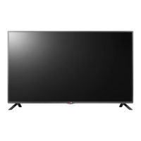
Lists the specific model numbers of the LED TV.
Important safety warning before performing any servicing.
Critical safety information and warnings for service personnel.
General safety practices and recommendations during servicing.
Procedure for checking AC leakage current while the set is powered.
Procedure for checking AC leakage current with the set unpowered.
Essential guidelines for safe and proper TV servicing.
Precautions for handling components sensitive to static electricity.
Recommended techniques and standards for soldering.
Method for removing and replacing Integrated Circuit components.
Procedure for removing and replacing discrete transistors.
Steps for replacing power output transistors, including heat sinks.
Method for removing and replacing diodes while maintaining polarity.
Procedure for replacing fuses and conventional resistors.
Techniques for repairing damaged circuit board foil patterns.
Defines the scope of the specification for the LED TV.
Specifies the environmental and power conditions for testing.
Outlines the procedures and standards for testing.
Details general specifications like market, broadcasting, and coverage.
Specifications for component video input signals and resolutions.
Specifications for different HDMI input modes and resolutions.
Specifications for PC input signals and resolutions.
Defines the scope of application for these adjustment instructions.
General designation and order for carrying out adjustments.
Procedures for Main PCB checks and boot file loading.
Steps for ADC calibration, function check, and display/sound verification.
Preparations required before starting assembly line adjustments.
Purpose and working principle of White Balance adjustment.
Guidelines for using automated control interfaces.
Map outlining RS-232C communication for auto adjustment.
Procedure for manual White Balance adjustment via remote control.
Specific adjustment procedure for the 'Cool' color temperature mode.
Adjustment procedures for 'Medium' and 'Warm' color temperature modes.
Procedure for writing EDID data via RGB connection.
Procedure for writing EDID data via HDMI connection.
Details on the format and content of EDID data.
Method for performing an automatic EDID data download.
Procedure for manually downloading EDID data.
Specific details and considerations for HDMI EDID data.
Content and structure of the EDID data.
Specific options and parameters within the EDID data.
Final configuration checks before the product leaves the factory.
Safety tests including ground continuity and high potential insulation.
Process for downloading and verifying model name and serial number.
Table detailing signal parameters and settings.
Set of commands used for various operations.
Important methods and notices related to procedures.
Check if the backlight is illuminated.
Verify power board outputs and cable connections.
Replace T-con board or display module if necessary.
Verify various voltage outputs from the power board.
Replace the main board if power issues persist.
Assess RF signal strength and quality using a meter or OSD menu.
Verify the current software version and check for SVC bulletins.
Inspect tuner soldering and consider Main Board replacement.
Verify RF signal cable integrity and external equipment.
Verify satellite settings, LNB frequency, and connection.
Check SW version, tuner soldering, and satellite settings.
Verify color issues across different input types (External, Component, RGB, HDMI).
Use test patterns and check the LVDS link cable for color issues.
Inspect external devices and cables for potential color errors.
Assess color conditions based on input types and screen state.
Perform software upgrade and use test patterns for diagnosis.
Verify external devices and LVDS link cable connections.
Verify the status and color of the front panel power LED.
Inspect power cord and measure DC output voltages from the power board.
Measure the standby 3.5V supply on the main board.
Replace the power board or main board if faults persist.
Inspect the power outlet and the AC power cord.
Check power off mode settings and CPU abnormality.
Verify voltage outputs from the power board.
Verify audio settings within the TV's user menu.
Measure audio B+ voltage and check speaker functionality.
Inspect the speaker connection for any disconnections.
Verify input signal, speaker, and connector status.
Measure the audio B+ voltage (24V) for proper operation.
Inspect external devices and their connections for audio issues.
Verify remote control operation and battery status.
Inspect IR cable connection and output signal.
Measure the 3.5V supply on the power board related to remote function.
Verify input signal and consult technical information for troubleshooting.
Apply fix information and check external devices.
Identify the type of noise and its location on the unit.
Replace PSU, LED driver, or display module based on noise severity.
Inspect for damage to the module, cabinet, remote control, or stand.
Replace any parts found to have exterior damage.
| Screen shape | Flat |
|---|---|
| Response time | - ms |
| Display diagonal | 47 \ |
| Display brightness | - cd/m² |
| LED backlighting type | - |
| Supported video modes | 1080p |
| Display diagonal (metric) | 100 cm |
| Screen format adjustments | 16:9 |
| Supported graphics resolutions | 1920 x 1080 (HD 1080) |
| Motion interpolation technology | MCI (Motion Clarity Index) |
| 3D | No |
| Annual energy consumption | 93 kWh |
| Tuner type | Analog & digital |
| Digital signal format system | DVB-C, DVB-T |
| Audio system | Virtual Surround |
| Audio decoders | Dolby Digital |
| RMS rated power | 20 W |
| Number of speakers | 2 |
| HDMI version | 1.4 |
| DVI-D ports quantity | 0 |
| USB 2.0 ports quantity | 1 |
| Consumer Electronics Control (CEC) | SimpLink |
| Number of OSD languages | 34 |
| Video formats supported | DIVX HD |
| Product color | Titanium |
| Panel mounting interface | 400 x 400 mm |
| Power consumption (standby) | 0.3 W |
| Power consumption (typical) | 64 W |
| Package weight | 16400 g |
| Cables included | AC |
| Sustainability certificates | RoHS |
| Depth (with stand) | 255 mm |
|---|---|
| Height (with stand) | 676 mm |
| Weight (with stand) | 12700 g |
| Depth (without stand) | 55.8 mm |
| Width (without stand) | 1073 mm |
| Height (without stand) | 629 mm |
| Weight (without stand) | 12300 g |