Do you have a question about the LG 49UH6500 and is the answer not in the manual?
| Screen shape | Flat |
|---|---|
| Response time | - ms |
| Display diagonal | 49 \ |
| Display brightness | - cd/m² |
| Native refresh rate | 60 Hz |
| Supported video modes | 2160p |
| Screen format adjustments | 16:9 |
| Supported graphics resolutions | 3840 x 2160 |
| Motion interpolation technology | TruMotion 120 Hz |
| 3D | No |
| Annual energy consumption | 104 kWh |
| Package depth | 174 mm |
| Package width | 1197 mm |
| Package height | 810 mm |
| Package weight | 17700 g |
| Product color | Silver |
| Panel mounting interface | 300 x 300 mm |
| Audio decoders | DTS, Dolby Digital |
| RMS rated power | 20 W |
| Number of speakers | 2 |
| Sustainability certificates | ENERGY STAR |
| AC input voltage | 100 - 240 V |
| AC input frequency | 50 - 60 Hz |
| Power consumption (standby) | 0.5 W |
| Cables included | AC |
| Operating system version | 3.0 |
| Operating system installed | Web OS |
| Wi-Fi standards | Wi-Fi 5 (802.11ac) |
| HDMI ports quantity | 3 |
| DVI-D ports quantity | 0 |
| USB 2.0 ports quantity | USB 2.0 ports have a data transmission speed of 480 Mbps, and are backwards compatible with USB 1.1 ports. You can connect all kinds of peripheral devices to them. |
| Ethernet LAN (RJ-45) ports | 1 |
| Consumer Electronics Control (CEC) | SimpLink |
| Number of OSD languages | 4 |
| Teletext function | - |
| Tuner type | Analog & digital |
| Analog signal format system | NTSC |
| Depth (with stand) | 282 mm |
|---|---|
| Height (with stand) | 702 mm |
| Weight (with stand) | 13700 g |
| Depth (without stand) | 77.2 mm |
| Width (without stand) | 1106 mm |
| Height (without stand) | 646 mm |
| Weight (without stand) | 9700 g |
Provides essential guidance for safe servicing practices and component handling.
Details the procedure for checking AC leakage current when the unit is powered on.
Describes the cold check for AC leakage current with the unit unplugged.
Covers general safety and handling procedures during receiver servicing operations.
Explains precautions for handling sensitive electronic components to prevent static damage.
Provides essential techniques and tips for proper soldering during repair procedures.
Details the method for removing and replacing integrated circuits on circuit boards.
Outlines the process for removing and replacing small-signal discrete transistors.
Explains how to remove and replace power output transistors and their associated heat sinks.
Provides instructions for safely removing and replacing diodes, observing polarity.
Details the procedure for replacing fuses and conventional resistors, including proper spacing.
Describes techniques for repairing damaged copper patterns on printed circuit boards.
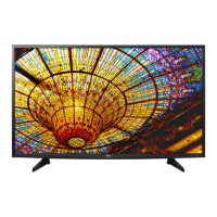
Defines the models and chassis for which this specification sheet is applicable.
Outlines the standard conditions required for testing TV performance and specifications.
Lists the methods and standards used for TV performance testing and specification verification.
Provides general technical specifications for the TV model, including market and broadcasting systems.
Lists detailed specifications for various screen sizes, aspect ratio, LCD modules, and operating environment.
Details specifications related to input voltage, display colors, and surface treatment for different modules.
Specifies input formats for 2D video signals, including component and HDMI inputs.
Lists component input resolutions, frequencies, and pixel clocks.
Details HDMI input resolutions, frequencies, pixel clocks, and proposed modes for PC and DTV.
Specifies automatic 3D HDMI input formats for version 1.4b, detailing resolutions and modes.
Lists manual 3D HDMI input formats for versions 1.4/2.0, including resolutions and modes.
Specifies manual 3D HDMI PC input formats, detailing resolutions, frequencies, and proposed modes.
Details manual and automatic 3D RF input modes and their signal compatibility.
Lists manual and automatic 3D USB/DLNA input modes and their parameters.
Lists manual 3D component input formats, including resolutions and frequencies.
Provides manual 3D input formats for Miracast and Widi, with resolutions and proposed modes.
Defines the application scope and general specifications for the adjustment process.
Lists the main adjustment items required for PCB and final assembly checks.
Details the process for automatic adjustment of ADC, including equipment and method.
Explains the procedure for downloading MAC address, ESN, Widevine, and HDCP2.0 keys.
Details the process of inspecting LAN connectivity, including PING test procedures.
Provides steps for performing a LAN port PING test using the relevant program.
Explains the process for downloading model name and serial number, including manual download.
Details how to check the Wi-Fi MAC address using RS232 commands.
Notes that ADC adjustment is not required due to the availability of Auto ADC adjustment.
Explains EDID and DDC download procedures for display identification and data exchange.
Provides reference information and details about EDID data structure and components.
Displays EDID block data for DTS HDMI1 with specific configuration.
Shows EDID block data for DTS HDMI2 with a specific configuration.
Shows EDID block data for DTS HDMI2 with a different configuration.
Displays EDID block data for DTS HDMI3 with a specific configuration.
Shows EDID block data for DTS HDMI3 with a different configuration.
Displays EDID block data for AC3 HDMI1 with a specific configuration.
Shows EDID block data for AC3 HDMI1 with a specific configuration.
Displays EDID block data for AC3 HDMI2 with a specific configuration.
Shows EDID block data for AC3 HDMI2 with a different configuration.
Displays EDID block data for AC3 HDMI3 with a specific configuration.
Shows EDID block data for AC3 HDMI3 with a different configuration.
Displays EDID block data for PCM HDMI1 with a specific configuration.
Shows EDID block data for PCM HDMI1 with a different configuration.
Displays EDID block data for PCM HDMI2 with a specific configuration.
Shows EDID block data for PCM HDMI2 with a different configuration.
Displays EDID block data for PCM HDMI3 with a specific configuration.
Shows EDID block data for PCM HDMI3 with a different configuration.
Lists checksum values for HDMI connections across different formats.
Details the V-COM adjustment procedure, including objectives and equipment.
Provides the command format and specific RS-232C commands used for V-COM adjustment.
Outlines the step-by-step method for performing the V-COM adjustment process.
Explains the objective and method for White Balance adjustment to reduce panel deviation.
Lists the RS-232C commands and protocol used for the White Balance adjustment.
Details the auto White Balance calibration procedure using the specified equipment and steps.
Provides a manual method for adjusting White Balance, including specific steps and cautionary items.
Presents reference data for White Balance adjustment coordinates and color temperature.
Provides a table of white balance values based on aging time for Edge and IOL LED modules.
Details the procedure for testing the Magic Motion remote control's functionality and pairing.
Explains how to perform a 3D function test using a pattern generator and specific test patterns.
Covers the inspection of HDMI ARC function, including test equipment and method.
Describes the procedure for inspecting the Eye-Q Green Function, including sensor testing.
Explains how to check the ship-out mode status before the unit is sent out.
Details the preparation and method for performing GND and internal pressure auto-checks.
Lists the checkpoints for voltage and test time during the GND and internal pressure check.
Specifies the conditions and methods for checking audio output levels and speaker performance.
Explains the optional service procedure for downloading software via USB.
Presents a block diagram illustrating the main components and connections of the M16 IC.
Shows the I2C map, detailing the connections and addresses for various I2C devices.
Illustrates the power distribution block diagram for the main board, showing DC DC converters and LDOs.
Depicts the schematic diagram of the tuner interface and its connections to the main IC.
Details the chip clock sources and their respective frequencies, including PLL outputs.
Provides an exploded view of the TV assembly, identifying major parts with reference numbers.
Details the steps for assembling latches and screws during the TV assembly process.
Illustrates the screw types, quantities, and torque specifications for disassembly.
Provides a visual guide and step-by-step instructions for disassembling the TV unit.
Provides an overview of the system configuration, including memory and interfaces.
Shows the NVRAM configuration and its connection to the M16 IC.
Lists the I2C addresses and functions for various components connected to the M16 IC.
Details the JTAG interface connections used for debugging purposes.
Explains the hardware model options and their corresponding settings for the M16 IC.
Shows the configuration for UART communication ports, including connections and settings.
Details the pinouts for various external connectors like HDMI and AV.
Illustrates the main I2S interface connections for audio processing.
Details the configuration and pin assignments for the DDR3 memory modules.
Provides pin assignments for DDR3 memory modules, including different capacities.
Shows various decoupling capacitor configurations for different power rails and ICs.
Illustrates the power wafer connections and voltage outputs for UHD models.
Details the panel power supply circuit, including the NIS5132MN2-FN-7 IC and its connections.
Shows the power detection circuit using the BD48K28G IC for monitoring various voltage levels.
Depicts a voltage regulator circuit providing a stable +3.3V_NORMAL output.
Shows a voltage regulator circuit for +1.5V DDR, including the BD9A300MUV IC.
Details a voltage regulator circuit providing +5V_NORMAL output using the BD86106EFJ IC.
Shows a voltage regulator circuit for +3.5V_ST using the SN1501019 IC.
Depicts a voltage regulator circuit providing +1.8V_IO output using the RT7295CG6F IC.
Provides a table correlating CORE_VID settings with VOUT and R2 resistor values.
Lists the CPU_VID settings, corresponding VOUT, and R2 resistor values for voltage control.
Details the power supply circuit for 0.9V DDR and C4TX using the TJ2132GDP IC.
Shows the Ethernet interface connections and cross-connection details for the RTL8201F IC.
Explains the control circuit for Wake-on-LAN (WOL) functionality.
Illustrates the pinout and connections for HDMI ports (2.0, 2.0 ARC, 1.4 Ext.EDID).
Details the HDMI receiver circuitry, including DDC pull-up resistors and ESD protection.
Shows the schematic for EDID external EEPROM and DDC buffer for HDMI3.
Illustrates the connections for AV jacks and the UART debug interface.
Depicts the pinout for the IR, Key, Wi-Fi, and BT wafer connector.
Details the connections for the Wi-Fi/BT connector, including power and control signals.
Shows the pinout and connection details for USB 2.0 ports.
Illustrates the USB 2.0 interface circuitry, including overcurrent protection.
Depicts the pinout and connection details for USB 3.0 ports.
Shows the USB 3.0 interface circuitry, including overcurrent protection.
Presents the schematic for the Ethernet interface, including the RJ45 connector and related components.
Details the LAN interface circuitry, including the Ethernet PHY IC and WOL control.
Shows the schematic for the front audio amplifier IC (NTP7515) and its connections.
Illustrates the speaker connections via a 4-pin wafer connector.
Depicts the headphone jack circuitry and its connections to the main board.
Shows the schematic for the earphone amplifier IC (TPA6138A2) and its audio output connections.
Presents the tuner circuit diagram, including RF connections, I2C control, and signal lines.
Illustrates the symbols and pinouts for various tuner connectors (TDJS-H301F, TDJA-T301F, etc.).
Details the power supply circuit for the demodulator, using the TJ2132GDP IC.
Shows the RS-232C control interface circuit for phone jack connection and communication.
Details the Vx1 B-lane video output signals and their input data format configurations.
Shows the VX1 lock status signal and related circuitry.
Illustrates the EPI interface connections for different EPI models, including power and signal lines.
Presents the power block schematic for the T-CON module, including various voltage regulators.
Details the PMIC boost/buck configuration for VDD and VCORE voltages, including options for different panel sizes.
Shows the eMMC interface connections and power supply for Toshiba and Samsung eMMC devices.
Shows dummy capacitor configurations for different models.
Lists the standard repair processes categorized by error symptoms and their corresponding pages.
Details the troubleshooting steps for 'No video/Normal audio' error symptoms.
Provides a flowchart for diagnosing and resolving 'No video/No audio' errors.
Outlines the flowchart for diagnosing and resolving picture issues like freezing or artifacts.
Provides a flowchart for diagnosing and resolving color-related display problems.
Provides a flowchart for diagnosing display issues like bars, residual images, and light spots.
Provides a flowchart for diagnosing and resolving TV power-related problems.
Outlines the flowchart for diagnosing and resolving power issues such as auto power off.
Provides a flowchart for diagnosing and resolving audio problems when video is present.
Outlines the flowchart for diagnosing and resolving audio distortion, noise, or interruption.
Details troubleshooting steps for remote control operational errors.
Outlines the flowchart for diagnosing and resolving MR15R Magic Remote control issues.
Provides a flowchart for diagnosing and resolving Wi-Fi connectivity problems.
Outlines the flowchart for diagnosing and resolving camera module issues.
Provides a flowchart for diagnosing and resolving issues with external device recognition.
Details troubleshooting steps for circuit and mechanical noise issues.
Provides a flowchart for diagnosing and resolving external physical damage to the TV.
Lists detailed technical manual contents for standard repair processes.
Continues the index of detailed technical manual contents for standard repair processes.
Details how to check and adjust White Balance for 'No video/Normal audio' issues.
Explains the TUNER input signal strength checking method for video lag/stop issues.
Details the version checking method using the IN-START remote control.
Describes the TUNER checking part and related troubleshooting steps.
Provides connection diagrams and checks for external input issues causing display problems.
Details how to check Link Cable (LVDS) reconnection for color errors.
Explains how to use test patterns via the ADJ key for video error diagnosis.
Shows visual examples of Main Board defects requiring replacement.
Provides more visual examples of Main Board defects that necessitate module exchange.
Shows visual examples of Power Board (PSU) issues like no light or dim light.
Illustrates cases of 'Un-repairable' module defects such as crosstalk and press damage.
Shows visual examples of un-repairable module defects like vertical/horizontal blocks or lines.
Details how to check the front power indicator for 'No power' issues.
Explains how to check power input voltage and ST-BY voltage for 'No power' issues.
Details the POWER OFF MODE checking method for power issues.
Explains how to check sound settings in the menu for 'No audio' issues.
Details voltage and speaker checking methods when there is no audio.
Provides steps to check IR cable and standby voltage for remote control issues.
Outlines steps to check motion cable and 3.3V for remote/Wi-Fi issues.
Outlines steps to check motion cable and 3.3V for remote/Wi-Fi issues.
Provides PCB layout diagrams for different TV models.
Details the changed features and specifications for the M16 chipset.
Shows the top and bottom side PCB views for CST solution.
Lists pin maps for 12-pin and 18-pin connectors related to power.
Explains HDMI 2.0a specifications and HDR static metadata extensions.
Provides PCB layout details for the 50/58UH63 model.
Shows PCB layout details for 43/49/55UH65 and 43UH75 models.
Details smart functions like CPU, GPU, OSD, HEVC, DDR, and Audio DSP.
Lists 4K capabilities including VP9, HDR, MEMC, NR/SR, and HDMI versions.
Provides specifications for T-con, Tuner, Multi-view, and Twin TV.
Shows top and bottom side PCB views for the CST solution on 50/58UH63 models.
Shows top and bottom side PCB views for the CST solution on 43UH65/43UH75 models.
Lists the pin assignments for the 12-pin power connector.
Lists the pin assignments for the 18-pin power connector with local dimming.
Explains HDMI 2.0a specifications and HDR static metadata extensions.
Details the structure and content of HDR static metadata blocks.