Service Manual 115
Control Devices and Function
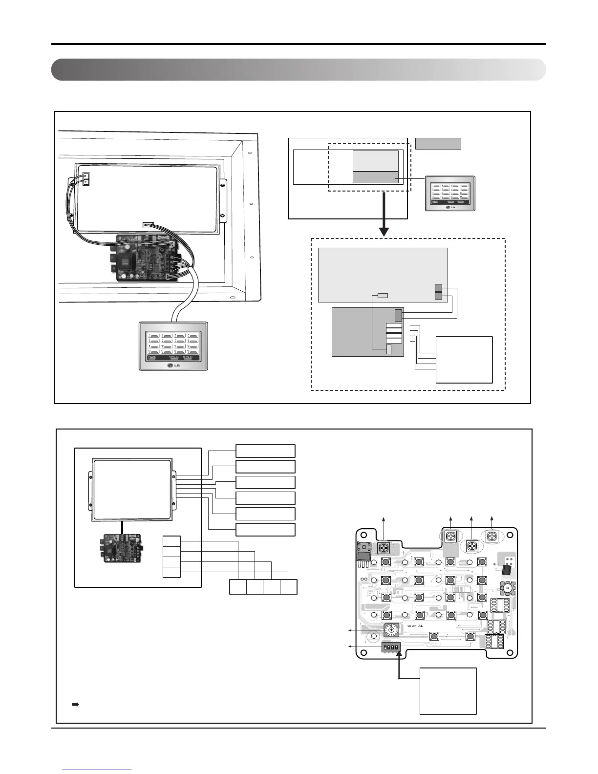
■ PICTORIAL VIEW OF THE CONNECTION
■ ONE SIMPLE CENTRAL CONTROL CONNECTION
Outdoor unit
Outdoor unit
Group Number 0
Master Mode
Vcc
GND
C
D
CN-POWER
GND
CN-COM A
S4
S3
S12
S16
TX1
LED4
LED8
LED12
LED11
LED16
LED15
PWB:6870A10001A
ASM:6711A20005E
LED7
LED3
L
+
+
+
+
+
+
+
+
+
S15
S18
S19
S15
S11
S2
LED2
S5
S9
+
+
+
S1
IC1P
LED5
LED9
LED13
LED17
LED10
LED14
S14
+
S6
S10
CN-POWER
CN-COM B
ON
L1 2 3 4
KSDO4H
: PNF-P14A0M
MAIN PCB
PI485
PI485
Control Box
All the connections are to be done as shown above.
A and B are the communication lines for the indoor and
C and D are the communication lines for the Central Control.
Use two shield lines for C/D connecting line.(Earth the shield line)
• Special purchase: Central control, PI485(PNF-P14A0M)
• SET The Address(Group No. & Indoor No.)
* Refer to The Following sheet
(1.3.5 Indoor unit Address setting method)
MAIN PCB
INDOOR UNIT
L
CN_CENTRAL
PI485
CENTRAL
CONTROL
UNIT
MAIN PCB
CN_CENTRAL
CN OUT
10
G
A
B
VCC
GND
C
D
N
L
OUTDOOR
MAIN PCB
INDOOR UNIT 1
INDOOR UNIT 2
INDOOR UNIT 3
INDOOR UNIT 4
INDOOR UNIT 5
INDOOR UNIT 6
Outdoor unit
Outdoor unit
BUS
B
D C GND VCC
BUS
A
GND
+10V
CENTRAL
CONTROL
UNIT
VCC
GND
C
D
 Loading...