GUIDELINES | 199
Application Guidelines
Due to our policy of continuous product innovation, some specications may change without notication.
© LG Electronics U.S.A., Inc., Englewood Cliffs, NJ. All rights reserved. “LG” is a registered trademark of LG Corp.
General Power Wiring / Communications Cable Guidelines
• Follow manufacturer’s circuit diagrams displayed on the inside of the control box cover.
• Have a separate power supply for the indoor units.
• Provide a circuit breaker switch between the power source and the indoor unit.
• Confirm power source specifications.
• Confirm that the electrical capacity is sufficient.
• Starting current must be maintained ±10 percent of the rated current marked on the name plate.
• Confirm wiring / cable thickness specifications:
• Power wiring is field supplied. Wire size is selected based on the larger MCA value, and must comply with the applicable local and
national codes.
• Communication cable must be a minimum of 18 AWG, two-conductor, twisted, stranded, shielded, and must comply with the applicable
local and national codes. Ensure the communication cable is properly grounded at the master outdoor unit only. Do not ground the
ODU-IDU communications cable at any other point.
• It is recommended that a circuit breaker is installed, especially if conditions could become wet or moist.
• Include a disconnect in the power wiring system. Add an air gap contact separation of at least 1/8 inch in each active (phase) conductor.
• Any openings where the field wiring enters the cabinet must be completely sealed.
APPLICATION GUIDELINES
Wiring Guidelines
1. Insert the power wiring / communications cable
from the outdoor unit or heat recovery unit
(Heat Recovery systems only) using the desig-
nated path in the indoor unit.
2. Connect each wire to its appropriate terminal
on the indoor unit control board. Verify that the
color and terminal numbers from the outdoor
unit or heat recovery unit (Heat Recovery sys-
tems only) wiring match the color and terminal
numbers on the indoor unit.
3. Secure the power wiring / communications
cable.
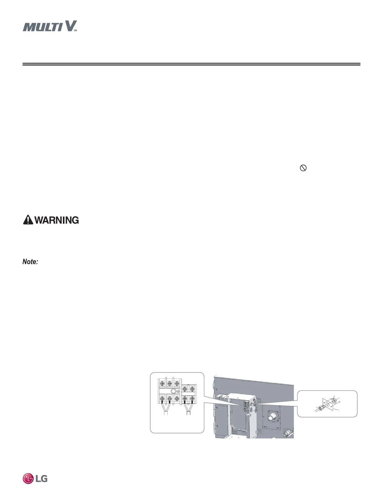
Power Wiring and Communications Cable Connections
Figure 76: Location of Power Wiring / Communications Cable Terminals in the High Static
BH, B8 and Low Static L1, L2, L3 Ducted Indoor Units (Appearances Vary Depending on
Model).
Lock nut
Conduit
mounting
plate
Conduit
L(L1)N(L2)
A B
Power Supply
High Voltage
(208/230V)
Communications
• Terminal screws may loosen during transport. Properly tighten the terminal connections during installation or risk equipment malfunc-
tion or property damage.
• Loose wiring may cause unit malfunction, the wires to burnout or the terminal to overheat and catch fire. There is a risk of equipment
malfunction or property damage.
A voltage drop may cause the following problems:
• Magnetic switch vibration, fuse breaks, or disturbance to the normal function of an overload protection device.
• Compressor will not receive the proper starting current.
• Terminal screws may loosen during transport. Properly tighten the terminal connections during installation or risk electric shock, physical
injury or death.
• Loose wiring may cause the wires to burnout or the terminal to overheat and catch fire. There is a risk of electric shock, physical injury
or death.
 Loading...