200 | GUIDELINES
MULTI V Ducted Indoor Unit Engineering Manual
Due to our policy of continuous product innovation, some specications may change without notication.
© LG Electronics U.S.A., Inc., Englewood Cliffs, NJ. All rights reserved. “LG” is a registered trademark of LG Corp.
Wiring Guidelines
APPLICATION GUIDELINES
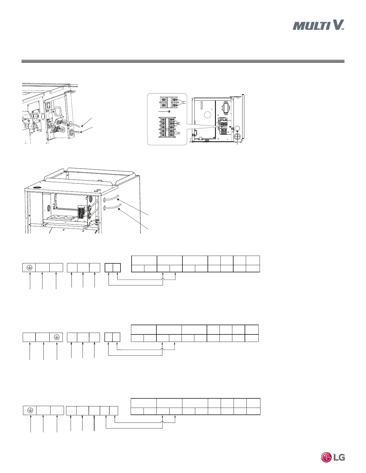
Power Wiring Through
Optional Access Hole
Communication Cable Through
Optional Access Hole
Figure 79: Terminal Block in the High Static BH Ducted Indoor Units.
Figure 77: Location of Power Wiring / Communications Cable Terminals in the High Static M2, M3 Ducted Indoor Units.
Indoor Unit Terminal Block
L(L1) N(L2)
A------ABB
GND 12V
DRY2DRY1
INTERNETIDUSODU
Outdoor Unit Terminal Block
Power Input
208-230V /
60 Hz / 1 Phase
Ground
YL RD
A B
BK
Wired Controller
Figure 78: Location of Power Wiring / Communications Cable Terminals in the Vertical / Horizontal Air Handler Unit.
Figure 80: Terminal Block in the High Static B8 Ducted Indoor Units.
Power Supply
High Voltage
(208/230V)
TransmissionWired Remote
Controller
YL RD BK A B
L(L1) N(L2)
GN/YL
Conduit Hole
Indoor Unit
Power Wiring
Remote Controller
Communications Cable
and Communications Cable
Between the Indoor Unit
and the Outdoor Unit
Figure 81: Terminal Block in the High Static M2, M3 Ducted Indoor Units.
Indoor Unit Terminal Block
L(L1) N(L2)
A - - - ---AB B
GND 12V
DRY2DRY1
INTERNETIDUSODU
Outdoor Unit Terminal Block
Power Input
208-230V /
60 Hz / 1 Phase
Ground
YL RD
A B
BK
Wired Controller
Indoor Unit Terminal Block
L(L1) N(L2)
A - - - ---AB B
GND 12V
DRY2DRY1
INTERNETIDUSODU
Outdoor Unit Terminal Block
Power Input
208-230V /
60 Hz / 1 Phase
Ground
YL RD
A B
BK
Wired Controller
 Loading...