52
ELECTRICAL WIRING
ENGLISH
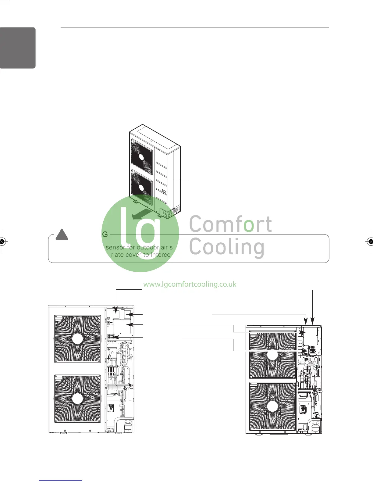
Control box and connecting position of wiring
- Remove all of the screws at side panel and remove the panel by pulling it forward.
- Connect communication cables between outdoor unit and indoor units through the terminal
block.
- When the central control system is connected to the outdoor unit, a dedicated PCB must be
connected between them.
- When connecting communication cable between outdoor unit and indoor units with shielded
cable, connect the shield ground to the earth screw.
Side panel
WARNING
The temperature sensor for outdoor air should not be exposed to direct sunlight.
- Provide an appropriate cover to intercept direct sunlight.
!
Indoor communication PCB
Main PCB
Terminal block
(Take care of the phase sequence
of 3-phase 4-wire power system)
PI485 PCB
(Inside the control box)
(Inside the control box)
※Pictures may differ depending on the model.
10HP/12HP4HP/5HP/6HP/8HP
1,MFL67798020, 2018. 4. 26. 7:06 Page 52
www.lgcomfortcooling.co.uk
 Loading...