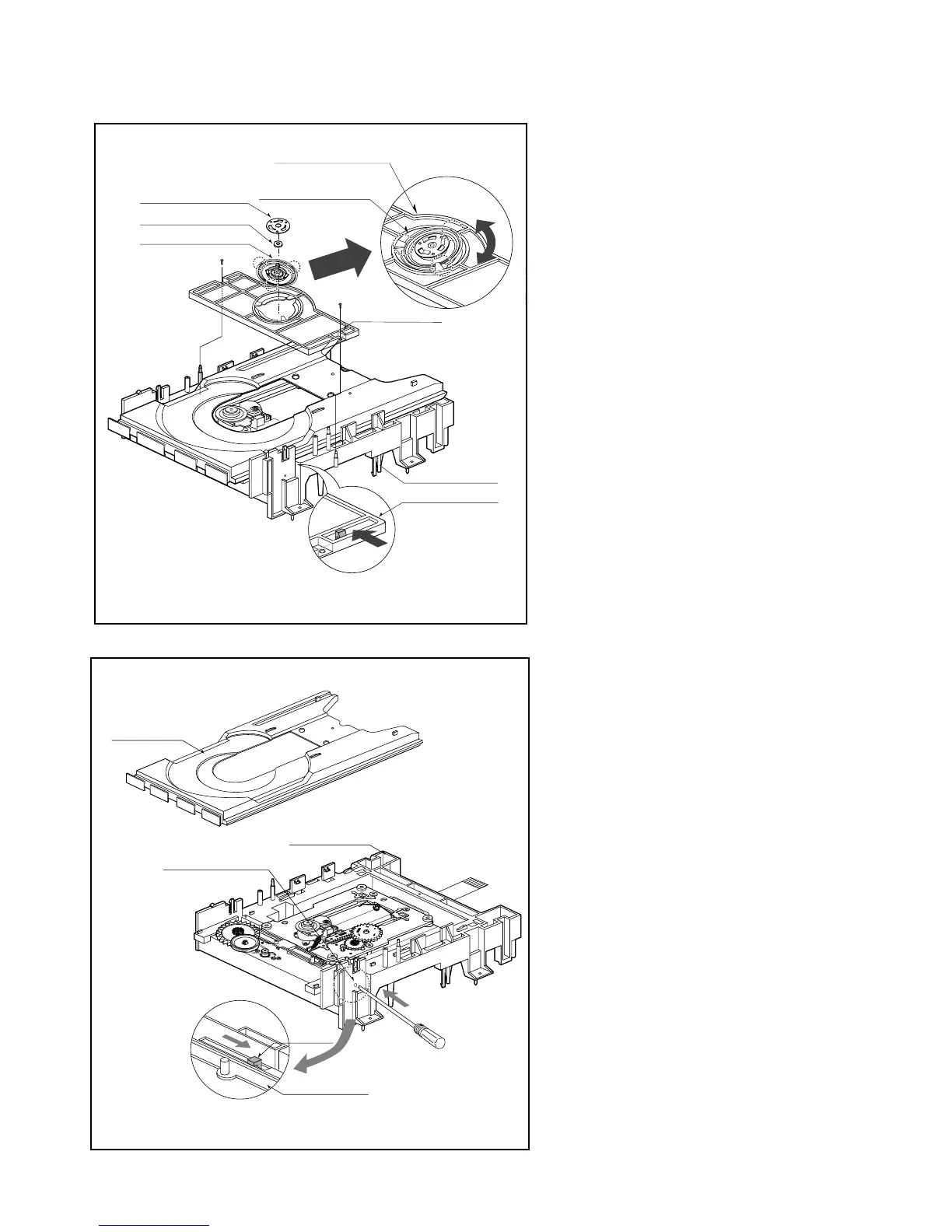
PLATE CLAMP
HOLDER CLAMP
TRAY DISC
BASE MAIN
LEVER
BASE MAIN
BOTTOM SIDE VIEW
EMERGENCY
EJECT HOLE
HOLDER CLAMP
BASE MAIN
HOLDER CLAMP
Fig. 4-1
Fig. 4-2
CLAMP ASSEMBLY DISC
MAGNET CLAMP
CLAMP UPPER
1. Holder Clamp (Fig. 4-1)
1) Release 2 Screws(S1).
2) Unhook 2 Locking Tabs(L1).
3) Lift up the Holder Clamp and then
separate it from the Base Main.
1-1. Clamp Assembly Disc
1) Place the Clamp Assembly Disc as
Fig. (A)
2) Lift up the Clamp Assembly Disc in
direction of arrow(A).
3) Separate the Clamp Assembly Disc from
the Holder Clamp.
1-1-1. Plate Clamp
1) Turn the Plate Clamp to
counterclockwise direction and then lift
up the Plate Clamp.
1-1-2. Magnet Clamp
1-1-3. Clamp Upper
2. Tray Disc (Fig. 4-2)
1) Insert and push a Driver in the
emergency eject hole(A) at the right
side, or put the Driver on the Lever(B) of
the Gear Emergency and pull the
Lever(B) in direction of arrow so that the
Tray Disc is ejected about 15~20mm.
2) Pull the Tray Disc until it is separated
from the Base Main completely.
(S1)
(L1)
(L1)
(A)
(S1)
(Fig.A)
(B)



 To Next Page