- 4-1 -
SECTION 4. MECHANISM
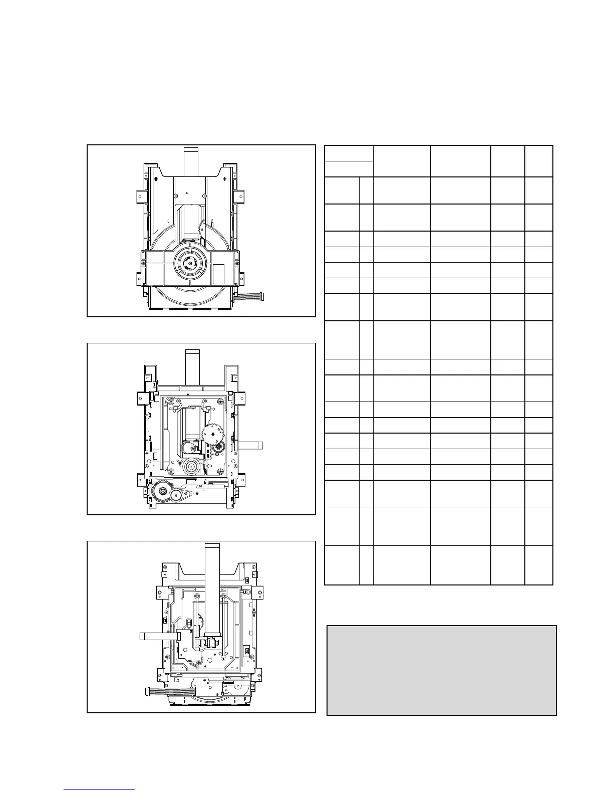
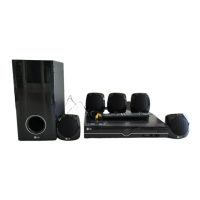
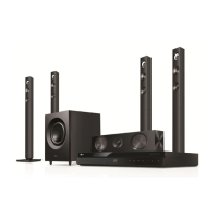
■ DECK MECHANISM PARTS LOCKATION
• Top View(With Tray)
Procedure
Parts
Fixing Type
Disass
Figure
Starting No. embly
1 Holder 2 Screws, 4-1
Clamp 2 Locking Tabs
12
Clamp Assmbly
2 Locking Tabs 4-1
Disc
1, 2 3 Plate Clamp 4-1
1, 2, 3 4 Magnet Clamp 4-1
1, 2, 3, 4 5 Clamp Upper 4-1
16Tray Disc 4-2
1, 6 7 Bass Assembly 4-3
Sled
4 Screws,
1, 2, 6 8 Gear Assmbly 1 Connector 4-3
Feed 1Locking Tabs
1, 2, 6, 8 9 Gear Middle 4-3
1, 2, 6, 10 Gear Assembly 1 Screw 4-3
8, 9 Rack
1, 2, 7 11 Rubber Rear 4-3
1, 2, 7 12
Frame Assembly
1 Screw Bottom 4-4
1, 2 13 Belt Loading 1 Locking Tab 4-4
1, 2, 13 14 Gear Pulley 4-4
1, 2, 13, 14
15 Gear Loading 1 Locking Tab 4-4
1, 2, 7, 12, 16 Guide Up/Down 4-4
13, 14
1, 2, 13 17 PWB Assembly 1 Locking Tab Bottom 4-4
Loading 1 Hook
2 Screw
1, 2, 7, 12, 18 Bass Main 2 Locking Tabs 4-4
13, 14, 15,
16, 17
Note
When reassembling, perform the procedure in
reverse order.
The “Bottom” on Disassembly column of above
Table indicates the part should be disassembled
at the Bottom side.
• Top View(Without Tray)
• Bottom View



 To Next Page