EasyManua.ls Logo

LG DLG2525S - User Manual

LG DLG2525S
41 pages
Print Icon
To Next Page IconTo Next Page
Loading...
U.S.A. Website: http://us.lgservice.com
Canadian Website: http://lg.ca
ELECTRIC & GAS DRYER
SERVICE MANUAL
CAUTION
READ THIS MANUAL CAREFULLY IN ORDER TO
PROPERLY DIAGNOSE PROBLEMS AND TO SAFELY
PROVIDE QUALITY SERVICE ON THESE DRYERS.
MODEL : DLE2512W/DLG2522W
DLE2514W/DLG2524W
DLE2515S / DLG2525S
TD-V10062G
Question and Answer IconNeed help?

Do you have a question about the LG DLG2525S and is the answer not in the manual?

LG DLG2525S Specifications

General IconGeneral
BrandLG
ModelDLG2525S
CategoryDryer
LanguageEnglish

Summary

IMPORTANT SAFETY NOTICE

General Safety Precautions

Essential safety guidelines, gas leak procedures, and ESD handling.

SPECIFICATIONS

Dryer Specifications

Technical details including size, capacity, and weight.

Available Accessories

Information on optional accessories like dryer rack, stacking kit, pedestal.

FEATURES AND BENEFITS

Drying Modes and Controls

Overview of sensor dry, manual dry, and control panel features.

INSTALLATION INSTRUCTIONS

Dryer Rack Installation

Step-by-step guide for installing the dryer rack.

Stacking Kit Installation

Safety Warning for Stacking

Critical warning regarding the need for two people for safe stacking.

Pedestal Installation

Pedestal Setup Steps

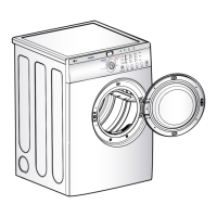
Instructions for positioning and securing the dryer on a pedestal.

ELECTRIC DRYER ELECTRICAL CONNECTIONS

4-Wire Receptacle Connection

Guide for connecting to a 4-wire receptacle.

3-Wire Receptacle Connection

Guide for connecting to a 3-wire receptacle.

Direct Wire Connection

Procedures for direct wiring electric dryers.

3-Wire Direct Connection Steps

4-Wire Power Cord Connection

3-Wire Power Cord Connection Options

Option 2: 3-Wire Power Cord

Connecting a 3-wire power cord per local codes.

Option 3: Optional 3-Wire Connection

Instructions for an optional 3-wire connection setup.

GAS DRYER GAS SUPPLY PIPE CONNECTION

Gas Supply Pipe Installation

Steps for connecting the gas supply pipe to the dryer.

DRYER CYCLE PROCESS OVERVIEW

Sensor Dry Cycles

Details on sensor dry cycles, including temperature and time.

Manual Dry Cycles

Details on manual dry cycles, including temperature and time.

Cycle Load Information

Information regarding motor and heater load during cycles.

COMPONENT TESTING INFORMATION

Thermal Cut-Off and Hi-Limit Thermostat Tests

Testing procedures for thermal cut-off and hi-limit thermostats.

Outlet Thermostat and Lamp Holder Tests

Testing procedures for outlet thermostats and lamp holder.

Door Switch and Idler Switch Tests

Testing procedures for door and idler switches.

COMPONENT TESTING PROCEDURES (CONTINUED)

Heater, Thermistor, and Motor Tests

Testing procedures for heater, thermistor, and motor components.

Gas Valve, Igniter, and Frame Detect Tests

Testing procedures for gas valve, igniter, and frame detect.

COMPONENT TESTING PROCEDURES (ADDITIONAL)

Outlet Thermostat Tests (Auto & Manual Reset)

Testing procedures for auto and manual reset outlet thermostats.

MOTOR DIAGRAM AND SCHEMATIC

Centrifugal Switch Operation

Diagram explaining centrifugal switch function in stop and run modes.

Motor Stop and Run Modes

Visual representation of motor operation states.

CONTROL LAYOUT AND DIAGNOSTIC TEST INFO

PWB Assembly Layout

Diagram showing the Printed Wiring Board assembly layout.

Model Diagnostic Display Mapping

Table linking models to diagnostic display and part numbers.

WIRING DIAGRAMS

Electric Dryer Wiring Diagram

Schematic showing electrical connections for electric dryers.

Gas Dryer Wiring Diagram

Schematic showing electrical connections for gas dryers.

DIAGNOSTIC TEST PROCEDURES

Activating Diagnostic Mode

Steps to enter the diagnostic test mode.

Diagnostic Test Sequences

Various test sequences based on button presses and door state.

TEST 1: 120 VAC ELECTRICAL SUPPLY

Electrical Supply Troubleshooting

Steps to diagnose lack of power to the controller.

TEST 2: THERMISTOR TEST

Thermistor Resistance Measurement

Procedure for measuring thermistor resistance at different temperatures.

Thermistor Resistance Table

Table correlating temperature with thermistor resistance.

TEST 3: MOTOR TEST

Motor Resistance and Operation Checks

Troubleshooting steps for motor rotation and fan function.

TEST 4: MOISTURE SENSOR TEST

Moisture Sensor Resistance and Voltage Checks

Procedure to test moisture sensor based on IMC and voltage.

IMC Ratio and Display Value Table

Table relating IMC ratio to display value and voltage.

TEST 5: DOOR SWITCH TEST

Door Switch Resistance Measurement

Steps to test door switch resistance based on door state.

TEST 6: HEATER SWITCH TEST - ELECTRIC TYPE

Heater Resistance and Thermostat Checks

Procedure to test heater resistance and safety thermostats.

TEST 7: GAS VALVE TEST - GAS TYPE

Gas Valve Voltage and Resistance Checks

Procedure to test gas valve voltage and terminal resistance.

CHANGE GAS SETTING (NATURAL GAS, PROPANE GAS)

Gas Setting Conversion Warning

Warning about improper conversion of gas settings.

Valve Setting Adjustment

Steps to adjust valve settings for different gas types.

Orifice Replacement Procedure

Guide for replacing the gas orifice.

GAS VALVE OPERATION FLOW

Gas Ignition Sequence

Flowchart illustrating the gas ignition process.

Gas Valve Structure Diagram

Visual representation of the gas valve's internal structure.

DISASSEMBLY INSTRUCTIONS - TOP PLATE

Removing the Top Plate

Step-by-step instructions for removing the top plate.

CONTROL PANEL ASSEMBLY DISASSEMBLY

Control Panel Disassembly Steps

Comprehensive steps to disassemble the control panel and PWB.

COVER CABINET DISASSEMBLY

Cabinet Cover Removal Steps

Instructions for disassembling the cabinet cover, including top plate and door.

TUB DRUM [FRONT] DISASSEMBLY

Front Tub Drum Removal Steps

Steps to disassemble the front tub drum assembly.

DRUM ASSEMBLY DISASSEMBLY

Drum Removal and Belt Adjustment

Instructions for removing the drum, including belt loosening.

CHANGING THE DRUM LAMP

Drum Lamp Replacement Procedure

Steps for replacing the drum lamp bulb.

DRYER EXHAUST DUCT CHANGE

Exhaust Duct Modification Steps

Instructions for changing the dryer exhaust duct configuration.

FILTER ASSEMBLY REMOVAL

Filter and Sensor Disconnection Steps

Steps to remove the filter and disconnect the electrode sensor.

BLOWER HOUSING DISASSEMBLY

Blower Housing Component Removal Steps

Steps to remove blower housing components like fan and motor.

BACK COVER REMOVAL

Back Cover Disassembly Steps

Instructions for removing the back cover.

AIR DUCT AND ROLLERS REPLACEMENT

Air Duct Removal Steps

Steps to remove the air duct.

Roller Removal Steps

Steps to remove the drum rollers.

EXPLODED VIEWS

Control Panel & Plate Assembly Exploded View

Exploded diagram of the control panel and plate assembly.

CABINET & DOOR ASSEMBLY EXPLODED VIEW

DRUM & MOTOR ASSEMBLY EXPLODED VIEW (ELECTRIC TYPE)

DRUM & MOTOR ASSEMBLY EXPLODED VIEW (GAS TYPE)

Related product manuals