Do you have a question about the LG Flatron F775FT and is the answer not in the manual?
Guidelines for servicing the color monitor, focusing on high voltage circuits.
Precautions regarding isolation transformers, lead dress, protective devices, and soldering.
Care needed to avoid damage to display tubes and their protection systems during installation.
Measures to prevent X-radiation by keeping high voltage at factory-recommended levels.
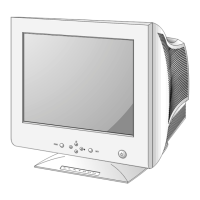
Button used to turn the monitor ON and OFF.
Indicator light color changes based on monitor status (normal, saving, abnormal).
Button to enter a selection in the on-screen display.
Controls for navigating and adjusting on-screen display menus.
Button to enter or exit the on-screen display.
Filters noise from the power input line and prevents interference with other appliances.
Eliminates abnormal color by degaussing the screen's shadow mask when the monitor is turned on.
Converts AC input voltage to various DC voltages required by monitor circuits.
Monitors high voltage and stops horizontal drive if it exceeds safety limits to prevent X-radiation.
Manages monitor operations, settings, and user adjustments via OSD.
Generates horizontal and vertical pulses for CRT deflection using H and V sync signals.
Steps up DC voltage from the SMPS to supply the horizontal deflection output circuit.
Improves screen distortion by correcting side-pincushion and trapezoid effects.
Drives the horizontal deflection yoke with a saw-tooth current for horizontal sweep.
Generates high voltage for the CRT anode, focus, and screen.
Corrects horizontal linearity based on the horizontal sync frequency.
Drives the vertical deflection yoke with a ramp wave for vertical sweep.
Maintains focus clarity across the screen by adjusting beam focus dynamically.
Controls retrace line elimination and screen brightness via G1 voltage.
Corrects screen tilt by supplying a signal to the tilt coil near the deflection yoke.
Amplifies the analog video signal to prepare it for further processing.
Amplifies the video signal for application to the CRT cathode.
Details on installing equipment and running alignment programs for monitor adjustments.
Procedure to adjust the high voltage to the factory-recommended level of 25.8kV.
Steps for setting factory presets, including clearing EEPROM and adjusting various parameters.
Guides for adjusting white balance, color bias, and luminance using specific patterns and meters.
Procedure to write EDID data to the EEPROM for monitor identification and configuration.
Steps to adjust the focus controls on the FBT for optimal screen clarity.
Flowchart to diagnose and identify causes of the monitor not powering on.
Flowchart to diagnose and identify causes of no image or characters appearing on the screen.
Flowchart to diagnose and identify causes of no display output (raster) on the screen.
Flowchart to diagnose and identify causes of missing horizontal image deflection.
Flowchart to diagnose and identify causes of horizontal linearity problems and related Cs signal table.
Flowchart to diagnose and identify causes of missing vertical image deflection.
Flowchart to diagnose and identify causes of issues with the On-Screen Display (OSD) functionality.
Flowchart to diagnose and identify issues related to the Digital Power Management (DPM) mode.
Flowchart to diagnose and identify causes of the degaussing function not working correctly.
Flowchart to diagnose and identify causes of the screen tilt or rotation function not working.
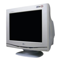
| Display Type | CRT |
|---|---|
| Maximum Resolution | 1280 x 1024 |
| Refresh Rate | 85 Hz |
| Aspect Ratio | 5:4 |
| Dot Pitch / Pixel Pitch | 0.25 mm |
| Max Resolution | 1280 x 1024 |
| Horizontal Refresh Rate | 30 - 95 kHz |
| Vertical Refresh Rate | 50 - 160 Hz |
| Input Signal | Analog RGB |
| Weight | 40.1 lbs |
| Dot Pitch | 0.25 mm |
| Screen Size | 17 inches |
| Viewable Size | 16 inches |