Do you have a question about the LG Flatron F900P and is the answer not in the manual?
Critical components are marked for safety. Handle with care.
Information on fire, shock, implosion, and X-radiation hazards.
Guidelines for measuring and preventing X-radiation exposure.
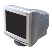
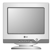
Details on front/rear views and operation of control panel buttons.
Explains USB features and how to connect peripherals.
Describes connecting various sync signals via BNC connectors.
Identifies VR801 for High Voltage and VR991 for B+ voltage.
Diagram showing DY assembly, degaussing, purity, and internal connectors.
Step-by-step guide for removing the tilt/swivel and back cover.
Describes SMPS, X-ray protection, and associated circuits.
Details Micom, sync processors, D/D converters, and deflection output.
Explains display power management, input signals, and OSD functions.
Covers H-linearity, vertical output, dynamic focus, and image rotation.
Describes video pre-amp and video output amplifier circuits.
Details high voltage output, blanking, brightness, and moire reduction.
Covers prerequisites, tools, and degaussing procedures.
Steps for adjusting B+ voltage and CRT anode high voltage.
Procedures for horizontal raster centering and factory preset mode calibration.
Guide for adjusting color balance and screen brightness.
Steps for adjusting the focus control on the FBT.
Flowchart for diagnosing power-related issues.
Flowchart for diagnosing power-related issues.
Flowchart for diagnosing issues with no character display.
Flowchart for diagnosing issues with no raster on screen.
Flowchart for troubleshooting vertical deflection problems.
Flowchart for diagnosing power management mode failures.
Flowchart for troubleshooting the degaussing function.
Flowchart for troubleshooting problems with the OSD system.
List of replacement capacitors with part numbers and specifications.
Continued list of replacement capacitors.
List of replacement diodes with part numbers and specifications.
List of replacement ICs, coils, and cores.
List of replacement coils and cores.
List of replacement transistors with part numbers and specifications.
List of replacement resistors with part numbers and specifications.
Continued list of replacement resistors.
Continued list of replacement resistors.
Continued list of replacement resistors.
List of other miscellaneous replacement components.
Provides pin configurations for key ICs like M62501P/FP, TDA8172, and M24C08.
Illustrations of main, interface, control, and video board component/solder sides.
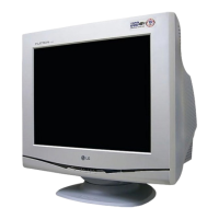
| Screen Size | 19 inches |
|---|---|
| Display Type | CRT |
| Maximum Resolution | 1600 x 1200 |
| Refresh Rate | 85 Hz |
| Aspect Ratio | 4:3 |
| Dot Pitch | 0.24 mm |
| Max Resolution | 1600 x 1200 |
| Horizontal Refresh Rate | 30 - 96 kHz |
| Vertical Refresh Rate | 50 - 160 Hz |
| Input Signal | RGB analog |
| Resolution | 1600 x 1200 |
| Viewable Size | 18 inches |
| Input Connectors | 15-pin D-Sub |