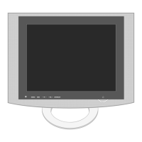
Do you have a question about the LG Flatron M198WA and is the answer not in the manual?
Identifies critical components essential for safety in LCD monitors.
Guidelines for safely handling the LCD module to prevent damage or injury.
Warnings and procedures related to high voltage and electric shock risks.
Provides a circuit diagram for testing leakage current.
General recommendations and precautions to follow during service operations.
Techniques to prevent damage to sensitive electronic components from static discharge.
Best practices for soldering and unsoldering components on circuit boards.
Step-by-step instructions for replacing ICs, transistors, diodes, fuses, and resistors.
Details general specifications related to TV functionality and inputs.
Technical specifications for RGB/DVI inputs and the LCD module.
Steps for removing the monitor stand base and cable management cover.
Procedures for separating the unit body and removing the back cover.
Steps for checking the main PCB and performing ADC calibration.
Verifies ADC adjustments and checks basic display/sound functions.
Procedures for color coordinate and auto-adjustment verification.
Lists adjustment commands and procedures for reading/writing EEPROM data.
Diagnostic steps for resolving power-on issues where the LED is off.
Troubleshooting steps for issues where no raster is displayed on the screen.
Diagnostic steps for resolving problems when no audio is produced.
Detailed schematic illustrating the connections and pins of the MSTAR processor.
Schematics for the standby and general voltage regulation circuits.
| Screen Size | 19 inches |
|---|---|
| Resolution | 1440 x 900 |
| Aspect Ratio | 16:10 |
| Panel Type | TN |
| Brightness | 250 cd/m² |
| Contrast Ratio | 1000:1 |
| Dynamic Contrast Ratio | 5000:1 |
| Response Time | 5 ms |
| Viewing Angle (Horizontal) | 170° |
| Viewing Angle (Vertical) | 160° |
| Input Ports | D-Sub, DVI-D |
| Input Connectors | D-Sub, DVI-D |


