Do you have a question about the LG Flatron T530S and is the answer not in the manual?
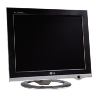
| Display Type | LCD |
|---|---|
| Dot Pitch | 0.297 mm |
| Max Resolution | 1024 x 768 |
| Bandwidth | 80 MHz |
| Input Signal | Analog RGB |
| Input Connector | 15-pin D-sub |
| Aspect Ratio | 4:3 |
| Response Time | 25 ms |
| Brightness | 250 cd/m² |
| Contrast Ratio | 400:1 |
| Screen Size | 15 inch |
| Horizontal Refresh Rate | 30-61 kHz |
| Vertical Refresh Rate | 50 - 75 Hz |
| Dimensions (W x H x D) | 370 x 380 x 180 mm |
Details about the monitor's picture tube, including size, deflection angle, and neck diameter.
Parameters for video input signals, sync polarity, impedance, and connectors.
Information on power range, consumption modes, and voltage.
Details on active video area, image sizes, colors, and resolution.
Operating conditions like temperature, humidity, and altitude.
Physical measurements and weight of the monitor with tilt/swivel.
Essential safety checks to be performed before servicing the monitor.
Precautions regarding electrical shock and fire risks during servicing.
Guidelines for handling the CRT's implosion protection system.
Measures to prevent X-radiation from the picture tube during operation.
Procedure for checking leakage current using a specific circuit diagram.
Essential guidelines for performing service safely and correctly.
Procedures for safely handling components sensitive to static electricity.
Best practices and techniques for soldering electronic components.
Steps for removing and replacing integrated circuits.
Methods for replacing small-signal and power transistors.
Steps for safely removing and installing diodes.
Procedures for replacing fuses and conventional resistors.
Techniques for repairing damaged copper traces on circuit boards.
Detailed timing values for horizontal sync, blanking, and porches.
Detailed timing values for vertical sync, blanking, and porches.
Instructions for removing the monitor's tilt/swivel mechanism and back cover.
Explanation of the power supply unit's operation and protection circuits.
Description of the circuit that protects the monitor from overvoltage.
Details on the DPM circuit for power saving modes and consumption.
Function of the MICOM for sync processing and user control via OSD.
Purpose of the D/D converter for high voltage control based on sync frequency.
Operation of the X-ray protection mechanism when high voltage is abnormal.
Function of the circuit correcting horizontal linearity for sync frequencies.
Description of the horizontal deflection amplifier for raster scan.
Function of the Automatic Beam Limiter circuit to limit beam current.
Explanation of the vertical deflection drive circuit using a ramp wave.
How blanking and brightness are controlled using G1 voltage.
Function of the circuit that corrects screen tilt using a tilt coil.
Description of the OSD display functionality for monitor status.
Details on the video drive and color compensation circuits.
Amplification of analog video signals from 0-0.7V to 0-4V.
Amplification of video signals for CRT cathode application.
Tools, equipment, and initial setup for monitor adjustments.
Method for accessing and performing adjustments via a service hotkey.
Parameters for focus, size, and centering adjustments using cross-hatch patterns.
Procedures for correcting display distortion and size drift.
Steps for adjusting linearity, voltage regulation, and trapezoid distortion.
Methods for setting pin balance and parallelogram correction.
Procedures for adjusting white balance and cut-off levels using specific patterns.
Steps to adjust the monitor's focus for a sharp image using the FBT VR.
Procedure for ensuring accurate color reproduction and alignment using purity magnets.
Steps for initial factory mode adjustments using alignment software.
Procedure for setting white balance and luminance using software and meters.
Diagnostic steps for when the monitor does not power on.
Troubleshooting steps for a blank screen or missing display content.
Steps to diagnose and resolve problems with the display raster.
Troubleshooting for vertical line display issues.
Diagnosing issues related to the Display Power Management modes.
Troubleshooting steps when the degaussing function fails.
Steps to diagnose and fix horizontal deflection problems.
Troubleshooting for problems with the horizontal size remaining constant.
Diagnosing and resolving issues with horizontal linearity.
Troubleshooting for incorrect horizontal image scaling.
Diagnosing issues with side pin and trap coil circuits.
Troubleshooting for parallelogram distortion and pin balance problems.
Troubleshooting for tilt adjustment issues.
Diagnosing problems with vertical size and position instability.
Steps to diagnose and resolve high voltage related issues.
Troubleshooting the ABL circuit for proper operation.
Diagnosing and resolving issues with the main microprocessor.
Troubleshooting problems with the OSD not appearing or functioning correctly.
Troubleshooting problems with front panel controls and buttons.
Diagnosing and resolving problems with one or more colors not displaying.
Troubleshooting steps for visible retrace lines on the screen.
Diagnosing and correcting color purity issues.
Steps to adjust and fix color misconvergence.
Troubleshooting steps for a blurry or unfocused display.