Do you have a question about the LG Flatron W2242T and is the answer not in the manual?
Details of the Thin Film Transistor Color LCD Module, including active display area and pixel pitch.
Specifications for viewing angle, luminance, and contrast ratio.
Sync signal type, video input signal details, and frequency ranges.
Supported analog and digital display resolutions.
Power adapter input and power consumption by mode.
Recommended temperature and humidity ranges for operation.
Width, depth, and height of the monitor with tilt.
Net and gross weight specifications.
Importance of specific safety components and original parts for preventing hazards.
Precautions for mounting, pressing, scratching, and grounding the LCD module.
Warnings about high voltage, especially with inverter circuits.
Recommendation to use plastic screwdrivers to prevent shock during service.
Standard procedures for unplugging, testing, and cleaning during service.
Techniques to prevent damage to sensitive electronic components from static electricity.
Guidelines for proper soldering iron use, solder type, and cleaning.
Methods for removing and replacing Integrated Circuits, transistors, and diodes.
Steps for replacing fuses and conventional resistors.
Techniques for repairing damaged copper traces on printed circuit boards using jumper wires.
Detailed table of horizontal and vertical timing specifications for various display modes.
Illustrated guide on how to take apart the monitor unit.
Overview of the main functional blocks and interconnections.
Explanation of the Video Controller, Power, and MICOM parts.
Block diagram and description of the power supply board (LIPS).
Procedure for configuring the system to run adjustment utilities.
Instructions for reading and writing Extended Display Identification Data.
Steps to enter the special service On-Screen Display menu.
Diagram illustrating the correct cable connections for service operations.
Diagnostic steps for a monitor that does not power on.
Steps to diagnose lack of display on the LIPS power board.
Steps to diagnose lack of display on the main board.
Diagnostic steps for issues related to the Display Power Management (DPM) function.
Schematic showing internal cable connections between components.
Visual representation of how the monitor is assembled.
List of part numbers and descriptions corresponding to the exploded view.
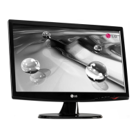
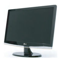
This document outlines the service and maintenance procedures for the LG Color Monitor, specifically the FLATRON W2242T series (models W2242T-SFT.AQ and W2242T-BFT.AQ). This service manual is intended for internal use by LG Electronics for training and service purposes, providing comprehensive information for technicians to effectively troubleshoot, repair, and maintain these LCD monitors.
The LG FLATRON W2242T is an LCD color monitor designed to display video signals from various sources. At its core, the monitor's functionality is managed by a video controller part, which is responsible for processing and converting video signals. This part amplifies analog video signals, converts them to digital, and utilizes a pixel clock for precise timing. The pixel clock operates within a range of 25MHz to 136MHz (or 28MHz to 146MHz depending on the specific W2242S case model). The video controller integrates a Scaler, an ADC converter, a TMDS receiver, and an LVDS transmitter. The Scaler is crucial for taking the converted analog-to-digital video signal, interpolating it to a 1680x1050 resolution, and then outputting an 8-bit R, G, B signal to the transmitter for display.
The monitor's power system is robust, featuring a power part that includes 3.3V and 1.8V regulators. These regulators convert the 5V power supplied by the power board to the necessary voltages for various components. Additionally, 22V is provided for the inverter, and 5V powers the LCD panel and the micom (microcontroller). The 5V supply is further regulated down to 3.3V and 1.8V for the main board's integrated circuits. The inverter is a critical component, converting the DC 22V to AC 700Vrms to operate the module's back-light lamps, ensuring proper screen illumination.
The MICOM part, which includes the video controller, houses an EEPROM IC for storing control data, a Reset IC, and the microcontroller itself. The micom intelligently identifies the polarity and frequency of the H/V sync signals received from the signal cable, and the control data for different operating modes is stored within the EEPROM.
The LIPS (LG Inverter Power Supply) board is a key element of the power system. It incorporates EMI components to meet global marketing EMI standards like FCC, VCCI CISPR, including a line-filter, line capacitor, and primary protection fuse. The input rectifier and filter convert the input AC voltage to a DC voltage via a bridge rectifier and a bulk capacitor. Energy transfer occurs through a power transformer, converting primary energy to secondary. The output rectifier and filter manage pulse width modulation control, providing driver signals to power switches and adjusting the duty cycle based on AC input and output loading to stabilize the DC output. It also monitors for over-power protection. A photo-coupler isolation mechanism feeds back DC output status to the primary controller, ensuring stabilized DC output voltage. Finally, a signal collection function gathers changes from the DC output and relays them to the primary via the photo transistor.
The LG FLATRON W2242T monitor offers a user-friendly interface for various display modes and adjustments. The monitor supports both analog and digital input signals, accommodating a wide range of devices. Its maximum resolution is 1680x1050 at 60Hz for both analog and digital inputs, providing clear and detailed visuals.
Power consumption is optimized, with the monitor consuming less than 45W (max) or 40W (typ) in normal operation, indicated by a blue LED. In standby, suspend, or DPMS (Display Power Management Signaling) off modes, power consumption drops to less than 1W, with an amber LED indicator. When the power switch is completely off, there is no power consumption.
The monitor features a Service OSD (On-Screen Display) menu, accessible by turning off the power, waiting 5 seconds, and then pressing the MENU and POWER switches for 1 second. This menu provides advanced calibration and diagnostic options. These include:
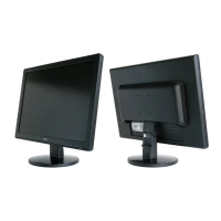
The monitor's physical design includes a base lock mechanism for easy assembly and disassembly of the stand and base cover. The control buttons are integrated into the cabinet, and the back cover can be disassembled for service access.
This service manual emphasizes safety and precision in all maintenance operations. Technicians are advised to follow strict safety precautions, particularly regarding safety-related components marked on schematic diagrams and parts lists. These critical parts must be replaced with manufacturer-specified components to prevent electric shock, fire, or other hazards. Unauthorized modifications are prohibited and will void warranties.
When handling the LCD module with the backlight unit, technicians must mount the module using all four corner mounting holes. Care must be taken not to press on the panel or its edges, scratch it with sharp objects, or expose it to ESD (Electrostatic Discharge), high temperatures, high humidity, or direct sunlight. Technicians are required to be grounded via a wrist band when working with the module. Cleaning the panel surface should only be done with a soft material to avoid damage. A plastic screwdriver is recommended for service operations to protect against shock hazards.
For soldering, a grounded-tip, low-wattage soldering iron with an appropriate tip size and shape (500°F to 600°F) and RMA resin-core solder (60% tin/40% lead) should be used. The soldering iron tip must be kept clean and tinned, and surfaces to be soldered must be thoroughly cleaned. Specific unsoldering and soldering techniques are detailed to prevent overheating circuit board foil.
Special procedures are outlined for removing and replacing various components:
Circuit board foil repair techniques are also provided for both IC connections and other areas. For IC connections, damaged copper patterns are removed, solder resist and acrylic coating are scratched away, and a small gauge jumper wire is crimped around the IC pin and soldered. For other connections, the defective copper pattern is removed, and an insulated 20-gauge jumper wire is connected between the nearest components on either side of the pattern break, crimped, and soldered, ensuring the jumper wire does not touch other components or sharp edges.
Troubleshooting guides are included for common issues such as "No Power," "No Raster (OSD not displayed) – LIPS," "No Raster (OSD not displayed) – Main," and "Trouble in DPM (Display Power Management)." These guides provide step-by-step diagnostic flows, including checks for voltage levels, pulses, crystal frequencies, and connection lines, often accompanied by waveform examples for visual reference. The EDID (Extended Display Identification Data) Read & Write procedure is also detailed, allowing technicians to edit and update manufacturing information and serial numbers using the WinEDID.exe tool.
| Screen Size | 22 inches |
|---|---|
| Resolution | 1680 x 1050 |
| Aspect Ratio | 16:10 |
| Panel Type | TN |
| Brightness | 300 cd/m² |
| Contrast Ratio | 1000:1 |
| Response Time | 5 ms |
| Viewing Angle (Horizontal) | 170° |
| Viewing Angle (Vertical) | 160° |
| Input Connectors | D-Sub, DVI-D |
| Power Consumption (Standby) | 1 W |