Do you have a question about the LG Flatron W2284F and is the answer not in the manual?
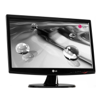
Details panel type, active display area, pixel pitch, size, and color depth.
Specifies viewing angles by contrast ratio, luminance, and contrast ratio.
Defines signal types, voltage levels, and input impedance for video signals.
States the display's maximum supported analog and digital resolutions.
Outlines power adaptor input, consumption, and LED color states.
Lists operating temperature, relative humidity, and MTBF for the unit.
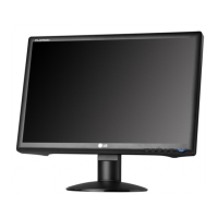
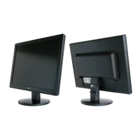
Provides the width, depth, and height of the monitor with tilt/swivel.
Specifies the net and gross weight of the monitor unit.
Details the pinout configuration for the DVI-D digital interface connector.
Highlights critical components for safety and warns against unauthorized modifications.
Provides guidelines for safely handling the LCD module and preventing damage.
Lists essential safety practices before and during receiver servicing operations.
Explains precautions for handling ESD-sensitive components to prevent damage.
Details proper techniques, tools, and materials for soldering electronic components.
Procedures for safely removing and replacing ICs, transistors, diodes, fuses, and resistors.
Step-by-step guide for repairing printed circuit board foil patterns at IC connections.
Method for repairing foil patterns at non-IC connections using jumper wires.
Explains the function of the video signal processing unit including Scaler and LVDS transmitter.
Describes the power regulators, 12V inverter, and power conversion for ICs.
Details the MICOM, EEPROM, control data, and sync signal distinction.
Explains the functional blocks of the LIPS power board, from EMI components to signal collection.
Guide for managing EDID data using WinEDID software for monitor configuration.
Lists and describes functions like CLEAR ETI, Auto Color, AGING, NVRAM INIT, and R/G/B adjustments.
Troubleshooting steps for when the monitor does not power on or indicator is off.
Diagnosing problems where the screen is blank or OSD is not visible, covering LIPS and Main circuits.
Steps to resolve issues related to the DPM function, checking sync pulses and PC modes.
Detailed schematic for the display scaler IC (TSUM058CWHJ) and related components.
Schematic diagram for the wafer section, including EEPROM and interface components.
Schematic of the power supply circuits, including DC-DC converters and voltage regulators.
Schematic detailing the user control buttons (Key 0, Key 1) and their interface.
| Screen Size | 22 inches |
|---|---|
| Resolution | 1680 x 1050 |
| Panel Type | TN |
| Aspect Ratio | 16:10 |
| Brightness | 300 cd/m² |
| Contrast Ratio | 1000:1 |
| Dynamic Contrast Ratio | 10000:1 |
| Response Time | 5 ms |
| Connectivity | VGA, DVI-D |
| Viewing Angles | 170° horizontal, 160° vertical |