Do you have a question about the LG Flatron W2442PA and is the answer not in the manual?
Details of the LCD panel, including type, size, and pixel pitch.
Optical properties like viewing angle, luminance, and contrast ratio.
Information about signal types, voltage levels, and frequencies.
Specifies the maximum supported display resolution.
Details about the power input and consumption levels.
Specifies operating temperature, humidity, and MTBF.
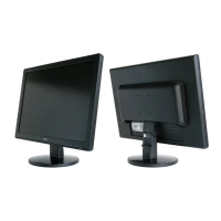
Provides the physical dimensions of the monitor.
Lists the net and gross weight of the monitor.
Pinout and signal assignments for the DVI-D digital connector.
Highlights critical components for safety and the need for manufacturer-specified parts.
Guidelines for safely handling the LCD module and preventing damage.
A general caution regarding tool usage for shock hazard prevention.
General guidelines for safe and proper servicing procedures.
Procedures to protect against static electricity damage to sensitive components.
Standard procedures and tips for effective soldering and unsoldering.
Detailed steps for removing and replacing integrated circuits.
Procedures for replacing small-signal and power transistors.
Methods for replacing diodes, fuses, and conventional resistors.
Instructions for repairing damaged copper patterns at IC connections using jumper wires.
Guidelines for repairing copper patterns at non-IC connections with jumper wires.
Explanation of the video signal processing and conversion components.
Description of the power supply and voltage regulation circuits.
Details about the microcontroller unit and its associated memory.
Visual representation of the LIPS (Local Interconnect Power Supply) board.
Explanation of the functional blocks within the LIPS board.
Steps for setting up the necessary ports for adjustment procedures.
Instructions for reading and writing Extended Display Identification Data (EDID).
Description of various functions and settings available in the Service OSD menu.
Troubleshooting steps for issues related to the monitor not powering on.
Diagnostic steps for no raster condition related to the LIPS board.
Steps for diagnosing no raster issues originating from the main board.
Steps to troubleshoot problems related to the Digital Picture Management (DPM) system.