EasyManua.ls Logo

LG FLATRON W2241S - User Manual

LG FLATRON W2241S
25 pages
Print Icon
To Next Page IconTo Next Page
Loading...
COLOR MONITOR
SERVICE MANUAL
Website:http://biz.LGservice.com
E-mail:http://www.LGEservice.com/techsup.html
CAUTION
BEFORE SERVICING THE UNIT,
READ THE SAFETY PRECAUTIONS IN THIS MANUAL.
CHASSIS NO. : LM73A
MODEL: W2241S(W2241S-BFT.A***P*)
( ) **Same model for Service
Internal Use Only
W2241S(W2241S-PFT.A***P*)
Question and Answer IconNeed help?

Do you have a question about the LG FLATRON W2241S and is the answer not in the manual?

Summary

Specifications

LCD Characteristics

Key physical and electrical properties of the LCD panel.

Optical Characteristics

Visual performance metrics like viewing angle, luminance, and contrast.

Signal (Refer to the Timing Chart)

Details on video input signals, sync types, and frequencies.

Max. Resolution

Maximum supported display resolution and refresh rate.

Power Supply

Power input, consumption, and adapter specifications.

Environment

Operating temperature, humidity, and MTBF.

Dimensions (with Tilt)

Physical size of the monitor with the stand.

Weight (with Tilt)

Weight of the monitor with the stand.

Precautions

Warning for Safety-Related Components

Identifies critical safety components and replacement warnings.

Handling the LCD Module with Backlight Unit

Guidelines for safely handling the sensitive LCD module.

General Servicing Precautions

Essential safety rules for servicing the unit, including power and discharge.

Electrostatically Sensitive (ES) Devices

Procedures to prevent damage to sensitive electronic components from static discharge.

General Servicing Guidelines

Best practices for soldering, unsoldering, and handling components.

IC Remove;Replacement

Specific techniques for removing and replacing integrated circuits.

Circuit Board Foil Repair

Methods for repairing damaged copper traces on circuit boards.

Timing Chart

Disassembly

Block Diagram

Description of Block Diagram

Video Controller Part

Explains the function of the video signal processing circuitry.

Power Part

Details the power supply stages and voltage regulation.

MICOM Part

Describes the microcontroller and its control functions.

Adjustment

Port Setup

Steps to configure the serial port for software interaction.

EDID Read & Write

Procedure for reading and writing monitor identification data.

Service OSD

Accessing Service OSD

Instructions on how to enter the service mode menu.

Service OSD Menu Options

Summary of functions available within the service menu.

Troubleshooting Guide

1. No Power

Diagnostic steps for when the monitor does not turn on.

2. No Raster (OSD Not Displayed) - LIPS

Troubleshooting a blank screen issue related to the LIPS board.

3. No Raster (OSD Not Displayed) - Main

Troubleshooting a blank screen issue on the main board.

4. Trouble in DPM

Steps to diagnose issues related to the Digital Picture Mode (DPM).

Wiring Diagram

Exploded View

Exploded View Parts List

Schematic Diagrams

Main Board Schematics

Detailed circuit diagram for the main control board.

Power & Wafer Schematics

Circuit diagrams for the power supply and related components.

LIPS Schematics

Circuit diagram for the LIPS (Low-power Image Processing System) board.

Inverter Schematics

Circuit diagram for the backlight inverter circuitry.

Overview

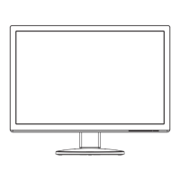
This document provides a comprehensive service manual for the LG COLOR MONITOR, specifically models FLATRON W2241S (W2241S-BFT.AP) and FLATRON W2241S (W2241S-PFT.AP), which share the same service model. The manual outlines the monitor's function, technical specifications, usage, and maintenance features, emphasizing safety precautions throughout.

Function Description

The LG COLOR MONITOR is a display device designed to process analog video signals, convert them into digital format, and display them on a TFT Color LCD Module. It incorporates a scaler to interpolate input signals to its native resolution, an ADC converter for analog-to-digital conversion, and an LVDS transmitter for efficient data transfer to the LCD panel. The monitor's power part manages voltage conversion and supplies power to various components, including the inverter for the backlight lamps. A MICOM (microcontroller) part, integrated with an EEPROM, stores control data and manages the monitor's operational modes based on H/V sync signals from the input.

Important Technical Specifications

LCD Characteristics

  • Type: TFT Color LCD Module
  • Active Display Area: 21.6 inch diagonal
  • Pixel Pitch: 0.27675 (H) x 0.27675 (V)
  • Size: 493.7(H) x 320.1(V) x 16.5(D)
  • Color Depth: 16.7M (6bit+HI FRC) color
  • Electrical Interface: LVDS
  • Surface Treatment: Anti-Glare, Hard Coating (3H)
  • Operating Mode: Normally White
  • Backlight Unit: 4 CCFL

Optical Characteristics

  • Viewing Angle by Contrast Ratio ≥ 5:
    • Left: -80° min., -85° (Typ)
    • Right: +80° min., +85° (Typ)
    • Top: +80° min., -85° (Typ)
    • Bottom: -80° min., -85° (Typ)
  • Luminance:
    • 180 (Typ) (Typ. ±30) - sRGB
    • 220 (min), 300 (Typ) - 6500K
    • 150 (min) - 9300K
  • Contrast Ratio:
    • 700 (min), 1000 (Typ)
    • DFC -> 8000:1 (Typ), 6400:1 (Min)

Signal (Refer to the Timing Chart)

  • Sync Signal Type: Separate Sync, SOG
  • Video Input Signal:
    • Type: R, G, B Analog
    • Voltage Level: 0~0.7 V
    • Input Impedance: 75 Ω
  • Operating Frequency:
    • Horizontal: 30~83kHz
    • Vertical: 56~75Hz

Maximum Resolution

  • Analog: 1680 x 1050 @ 60Hz

Power Supply

  • Power Adaptor (Built-in Power) Input: AC 100-240V~, 50/60Hz, 1.0A
  • Power Consumption (Normal): Less than 45 W (max), less than 40 W (typ)
  • Power Consumption (Stand By, Suspend, DPMS Off, Power S/W Off): Less than 1 W

Environment

  • Operating Temperature: 10°C~35°C (50°F~95°F)
  • Relative Humidity: 10%~80% (Non-condensing)
  • MTBF: 50,000 HRS with 90% Confidence level
  • Lamp Life: 50,000 Hours (Min)

Dimensions (with TILT)

  • Width: 515.7 mm (20.30")
  • Depth: 209.4 mm (8.24")
  • Height: 418.0 mm (16.46")

Weight (with TILT)

  • Net. Weight: 4.05kg (9 lbs)
  • Gross Weight: 5.55kg (12.33 lbs)

Usage Features

The monitor supports various display modes, with detailed timing charts provided for resolutions ranging from 640x400 to 1680x1050. Users can access a Service OSD (On-Screen Display) menu for advanced adjustments and diagnostics. This menu is accessed by turning off the power, waiting 5 seconds, and then pressing the MENU and POWER switches for a 1-second interval.

The Service OSD menu includes features such as:

  • CLEAR ETI: To initialize using time.
  • Module: To select the applied module.
  • Auto Color: For W/B balance and automatic setting of gain and offset values (press key for over 3 sec).
  • AGING: To select Aging mode (on/off).
  • NVRAM INIT: EEPROM initialization (24C16, press key for over 3 sec).
  • R/G/B-9300K / R/G/B-6500K: Allows manual setting of R/G/B values for specific color temperatures.
  • R/G/B-Offset / R/G/B-Gain: Allows manual setting of R/G/B offset and gain values (Analog Only).

The manual also includes instructions for EDID (Extended Display Identification Data) read and write operations using the WinEDID.exe tool, which is crucial for configuring display parameters and ensuring compatibility.

Maintenance Features

The manual provides detailed instructions and precautions for servicing the unit, emphasizing safety and proper handling of components.

Safety Precautions

  • Safety-Related Components: Special components marked in the schematic diagram and parts list are critical for safety and must be replaced with manufacturer-specified parts to prevent electric shock, fire, or other hazards.
  • Modifications: Do not modify the original design without written permission from the manufacturer.
  • High Voltage: Exercise extreme caution when working with the inverter circuit, as high voltages (up to 650Vrms) are present. Always disconnect AC power before servicing.
  • ESD Protection: Protect the LCD module from electrostatic discharge (ESD) by grounding the treatment person's body with a wrist band and handling components on a conductive surface.
  • Physical Handling: Avoid pressing on the panel or frame edges, scratching the panel with sharp objects, or exposing the module to high temperatures, high humidity, or direct sunlight.
  • Cleaning: Use a soft material to wipe the panel surface; avoid dirty or rough cloths.
  • Tools: Use only a plastic screwdriver to protect against shock hazards during service.

Servicing Precautions

  • Power Disconnection: Always unplug the AC power cord before removing/reinstalling components, disconnecting electrical connections, or discharging the picture tube anode.
  • Electrolytic Capacitors: Ensure correct part substitution and polarity installation to prevent explosion hazards.
  • High Voltage Testing: Use appropriate high voltage meters; do not test by "drawing an arc."
  • Picture Tube Anode Discharge: Follow specific grounding procedures to safely discharge the anode.
  • Chemicals: Do not spray chemicals on or near the receiver.
  • Electrical Contacts: Clean contacts with a mixture of 10% Acetone and 90% Isopropyl Alcohol.
  • Heat Sinks: Ensure all solid-state device heat sinks are correctly installed before applying AC power.
  • Grounding: Always connect the test receiver ground lead first and remove it last.
  • ES Devices: Handle electrostatically sensitive devices (ICs, transistors, chip components) with care, using grounded tools and anti-static practices. Remove ES devices from protective packaging only when ready to install.

Soldering Guidelines

  • Tools: Use a grounded-tip, low-wattage soldering iron (500°F-600°F) and RMA resin-core solder (60% tin/40% lead).
  • Technique: Follow specific procedures for unsoldering and soldering to avoid overheating circuit board foil.
  • IC Removal/Replacement: Special techniques are provided for ICs with slotted holes, including straightening leads and using suction-type solder removal.
  • Discrete Transistor/Diode/Fuse/Resistor Replacement: Detailed steps are given for replacing these components, including clipping leads, crimping, soldering, and maintaining original spacing to prevent overheating.

Circuit Board Foil Repair

  • IC Connections: Instructions for repairing damaged copper patterns at IC connections using jumper wires.
  • Other Connections: Techniques for repairing defective copper patterns at other connections on the component side of the board, ensuring proper insulation and dressing of jumper wires.

Troubleshooting Guide

The manual includes flowcharts for diagnosing common issues such as "NO POWER," "NO RASTER (OSD IS NOT DISPLAYED) – LIPS," "NO RASTER (OSD IS NOT DISPLAYED) – MAIN," and "TROUBLE IN DPM." Each flowchart guides the technician through a series of checks, including voltage measurements at specific pins (e.g., J703, U602, U601, U501) and crystal frequency checks, with corresponding waveform examples for visual reference. This systematic approach helps identify the root cause of the problem, whether it's related to the power board, main board, inverter, or LCD module.

LG FLATRON W2241S Specifications

General IconGeneral
BrandLG
ModelFLATRON W2241S
CategoryMonitor
LanguageEnglish

Related product manuals