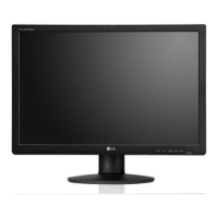
Do you have a question about the LG Flatron W1943SB and is the answer not in the manual?
Critical safety components must be replaced with manufacturer-specified parts to prevent hazards.
Guidelines for safely handling the LCD module to prevent damage and ensure proper mounting.
Warning about electric shock, especially when dealing with high voltage components like the inverter.
Caution to use plastic tools for shock hazard protection during service.
General guidelines for safely servicing the unit, including power disconnection and high voltage handling.
Procedures to prevent damage to ES devices from static electricity during handling and repair.
Best practices for soldering, including iron temperature, solder type, and tip maintenance.
Step-by-step guide for removing and replacing Integrated Circuits (ICs) on circuit boards.
Procedures for replacing discrete transistors, including small-signal and power types.
Method for safely removing and replacing diodes, emphasizing polarity and lead bending.
Steps for replacing fuses and conventional resistors, noting spacing for component temperature.
Techniques for repairing damaged copper patterns on circuit boards using jumper wires.
Detailed timing specifications for video and sync signals across different display modes.
Steps to detach the monitor base, starting with placing it on a flat surface and releasing a button.
Instructions for removing the front cover by pulling it upward after separating latches.
Steps to remove the back cover by placing the monitor face down and disassembling the rear section.
Steps to pull out the keyboard from the bezel and then disassemble the bezel itself.
Instructions for disconnecting the LVDS cable and removing connectors.
Steps to separate the main board/power board from the panel.
Steps to detach the rear cover and hinge assembly.
Details on disassembling the hinge and stand components.
Overview of the main board's functional blocks including Scalar, Flash, Crystal, and power regulators.
Schematic showing the power conversion stages from AC input to DC outputs like 5V and 14.5V.
Diagram illustrating the inverter's function, including PWM IC, lamp drive, and protection circuits.
Explanation of the Video Controller's role in signal amplification, digital conversion, and pixel clock generation.
Description of power distribution, voltage regulation, and inverter operation for backlights.
Details on the Microcomputer unit's functions, including sync signal processing and mode control.
Diagram of the LIPS board showing its functional blocks and operation.
Explanation of the LIPS board's functional blocks and their roles in power management and stabilization.
Configuration steps for parallel port settings required for EDID programming.
Procedure for writing EDID data to the monitor using specific software and hardware.
Checking manufacturer name, model, serial number, and checksum for successful EDID record.
Steps to enter the service mode by turning off power and pressing specific buttons.
Overview of available service menu options like Auto Color, Aging, and R/G/B adjustments.
Diagram showing cable connections for Micom uploading to the monitor.
Flowchart to diagnose no power issues, checking AC input, voltage levels, and crystal oscillation.
Diagnostic steps for no raster/OSD display, checking power board, voltage, and scaler IC.
Troubleshooting for no raster/OSD display on MSTAR platform, checking scaler oscillation and sync signals.
Steps to diagnose DPM issues by checking scaler sync signals.
Diagnostic flowchart for power problems, checking AC line, voltages, and internal power components.
Steps to troubleshoot raster issues when the lamp is off, checking power, signals, and backlight components.
Diagram illustrating the wiring connections between major components of the monitor.
Visual representation of the monitor's components in an exploded format for identification.
List of parts with their reference numbers, TPV part numbers, LGE part numbers, and descriptions.
List of replacement capacitors for the main board with part numbers and specifications.
List of replacement diodes, ICs, transistors, and resistors for the main board.
List of replacement resistors, fuses, and connectors for the main board.
List of replacement capacitors for the power board with part numbers and specifications.
List of replacement diodes, ICs, transistors, and resistors for the power board.
List of replacement resistors, transformers, and connectors for the power board.
List of replacement parts including wire harnesses, fuses, jumper wires, and filters.
Comparison of parts between W1943SB and T8RGNFNBMWLFNN models for identifying differences.
Schematic showing the scaler's input signals and panel interface connections.
Schematic detailing the connections for the D-SUB input port and associated components.
Schematic detailing connections for major ICs like Scalar (U401), Flash (U402), and others.
Detailed schematic of the CN405 panel connector, showing LVDS and control signal pinouts.
Schematics for voltage regulators U701-U704 providing 3.3V and 1.8V to the system.
Detailed schematic of the power supply section, including AC input, filtering, transformer, and output stages.
Schematic of the inverter circuit, showing its components and connections for driving CCFL lamps.



 Loading...