Do you have a question about the LG Flatron W1642C and is the answer not in the manual?
Details about the LCD panel's physical and visual properties.
Information on viewing angles and contrast ratio.
Technical specifications for video and sync input signals.
Defines the monitor's maximum supported display resolution.
Details on the monitor's power input and consumption.
Operating conditions and expected lifespan (MTBF, Lamp Life).
Physical measurements of the monitor unit.
Weight specifications for the monitor unit.
Critical safety components and replacement guidelines.
Warning about using plastic screwdrivers to avoid shock.
General safety guidelines for servicing the unit.
Precautions for handling sensitive electronic components.
Explanation of the video signal processing and conversion circuit.
Description of the power supply regulation and distribution system.
Details on the microcontroller unit and its control functions.
Functional description of the LIPS power supply board.
Procedure for configuring the communication port for adjustments.
Instructions for reading and writing monitor EDID data.
Menu option to initialize the unit's usage time.
Menu option for selecting the applied display module.
Menu option for automatic white balance and color adjustment.
Menu option to initialize the EEPROM settings.
Menu option for manual R/G/B adjustment at 9300K.
Menu option for manual R/G/B adjustment at 6500K.
Menu option for manual R/G/B offset adjustment (Analog).
Menu option for manual R/G/B gain adjustment (Analog).
Diagnostic steps for when the monitor does not power on.
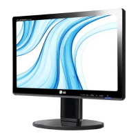
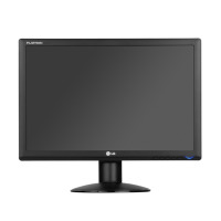
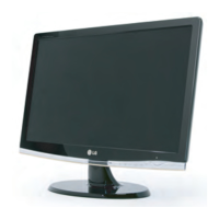
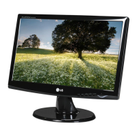
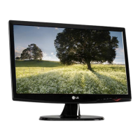
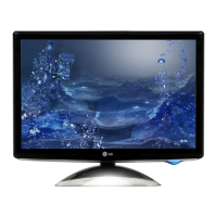
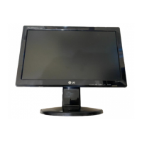
This document outlines the service procedures and features for the LG FLATRON W1642C (W1642C-PFT.A**AP) color monitor, chassis LM73B. It is intended for internal use by service personnel and provides comprehensive information for maintenance and repair.
The LG FLATRON W1642C is a color monitor designed to display video signals from a connected source. Its core function involves processing analog video input signals, converting them to a digital format, and then displaying them on a Thin-Film Transistor (TFT) Color Liquid Crystal Display (LCD) module. The monitor supports a maximum resolution of 1360 x 768 at 60Hz in analog mode.
The monitor's internal architecture includes a Video Controller Part responsible for amplifying and converting analog video signals to digital. This part utilizes a pixel clock, generated by a Phase-Locked Loop (PLL), which can range from 25MHz to 136MHz (or 28MHz to 146MHz in some cases). Key components within the video controller include a Scaler, an Analog-to-Digital Converter (ADC), a Transition Minimized Differential Signaling (TMDS) receiver, and a Low-Voltage Differential Signaling (LVDS) transmitter. The Scaler interpolates input signals to the native 1360 x 768 resolution and outputs 8-bit Red, Green, and Blue (RGB) signals to the transmitter.
The Power Part of the monitor is responsible for supplying the necessary voltages to various internal components. It includes 3.3V and 1.8V regulators that convert the 5V power supplied by the power board. Additionally, 18V is provided for the inverter, and 5V is supplied to the LCD panel and the Microcontroller (MICOM). The inverter converts DC 18V to AC 700Vrms to power the backlight lamps of the LCD module.
The MICOM Part integrates the video controller and includes an EEPROM (Electrically Erasable Programmable Read-Only Memory) IC, which stores control data, a Reset IC, and the MICOM itself. The MICOM identifies the polarity and frequency of the Horizontal (H) and Vertical (V) sync signals received from the signal cable, with controlled data for different display modes stored in the EEPROM.
The LIPS (LG Inverter Power Supply) Board, a critical component, handles power management. It comprises EMI (Electromagnetic Interference) components to comply with global marketing standards, an input rectifier and filter to convert AC voltage to DC, an energy transfer section utilizing a power transformer, and an output rectifier and filter for pulse width modulation control and output stabilization. A photo-coupler isolation mechanism feeds back DC output status to the primary controller, ensuring a stabilized DC output voltage. Signal collection functions gather changes from the DC output and feed them back to the primary via the photo-transistor.
The monitor is designed for ease of use and offers several operational modes and settings. Power consumption varies depending on the mode: less than 20W (max) or 18W (typ) in normal active mode (indicated by a blue LED), and less than 1W in stand-by, suspend, or DPMS (Display Power Management Signaling) off modes (indicated by an amber LED). When the power switch is off, consumption is also less than 1W, with no LED indication.
Users can access a Service OSD (On-Screen Display) menu for advanced adjustments and diagnostics. This menu is accessed by turning off the power, waiting 5 seconds, and then pressing the MENU and POWER switches for a 1-second interval. The Service OSD provides functions such as:
The monitor supports various display resolutions and timing charts, including 720x400, 640x480, 800x600, 832x624, 1024x768, and 1280x768, up to its maximum of 1360x768. These timings are crucial for ensuring compatibility with different video sources.
The service manual emphasizes safety precautions and detailed procedures for maintenance and repair. Safety Precautions:
Handling the LCD Module with Backlight Unit:
Servicing Procedures:
Troubleshooting Guide: The manual includes flowcharts for diagnosing common issues:
The document also provides wiring diagrams and an exploded view with a parts list, including safety-marked components, to facilitate accurate identification and replacement of parts during service.
| Screen Size | 16 inches |
|---|---|
| Resolution | 1366 x 768 |
| Panel Type | TN |
| Brightness | 250 cd/m² |
| Contrast Ratio | 1000:1 |
| Response Time | 5 ms |
| Connectivity | VGA |
| Aspect Ratio | 16:9 |