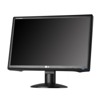
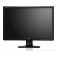
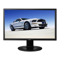
Do you have a question about the LG Flatron W2600H and is the answer not in the manual?
Critical safety components and handling guidelines.
Guidelines for safely handling the LCD module and backlight unit.
High voltage warnings and precautions for servicing.
General safety practices for unit servicing, including power and cleaning.
Precautions and techniques to prevent damage from static electricity.
Best practices for soldering and unsoldering components on circuit boards.
Step-by-step guides for removing and installing various electronic components.
Techniques for repairing damaged copper patterns on circuit boards.
Details on LCD type, size, pixel pitch, color depth, and electrical interface.
Viewing angle, luminance, contrast, resolution, and signal types.
Power supply, operating environment, dimensions, and weight details.
Diagrams illustrating horizontal and vertical synchronization timing signals.
Tables detailing timing parameters for various video input modes.
Covers adjustment scope, appointment, overview, and board-level procedures.
Detailed steps for color coordinates and luminance adjustments.
Confirms operation modes, quality, OSD, DPM, and USB functionality.
Instructions for EDID data writing, reading, and editing using Windows utilities.
Steps to access and use the Service OSD menu for adjustments.
Description of various options available within the Service OSD menu.
Steps to diagnose and resolve power-on issues.
Visual guides for interpreting waveforms during troubleshooting.
Troubleshooting steps for no display raster or OSD related to the inverter.
Troubleshooting steps for no display raster or OSD related to the main board.
Steps to diagnose and resolve issues related to Digital Power Management.
Block diagram of the main controller, LVDS interface, and digital video processor.
Block diagram of input interfaces (D-SUB, DVI) and memory (EEPROM, Flash, SDRAM).
Block diagram of power supply, inverter, and USB hub sections.
Explanation of the video signal amplification, digital conversion, and scaling process.
Explanation of the power supply regulators and MICOM's role.
Describes EMI, Input Rectifier, Energy Transfer, and Output Rectifier functions.
Explains Photo-Coupler Isolation and Signal Collection operations.
Visual representation of the monitor's internal components in an exploded view.
Circuit diagrams for input interfaces and the scaler section.
Circuit diagrams for the scaler and video processing components.
Circuit diagrams for the power supply unit (LIPS board).
Circuit diagrams for the USB controller and ports.
Circuit diagrams for the control buttons and key input interface.
Circuit diagrams related to the power management and LED indicators.
Circuit diagrams detailing USB connectors and their pin assignments.
Layouts for the main printed circuit board (top and bottom views).
Bottom-side layout of components on the main printed circuit board.
Layouts for the control board (top and bottom views).
Layouts for the power and LED board (top and bottom views).
Layouts for the USB board (top and bottom views).
| Screen Size | 26 inches |
|---|---|
| Resolution | 1920 x 1200 |
| Aspect Ratio | 16:10 |
| Brightness | 400 cd/m² |
| Contrast Ratio | 1000:1 |
| Response Time | 5 ms |
| Panel Type | TN |
| Dynamic Contrast Ratio | 3000:1 |
| Connectivity | DVI-D, VGA |
| Viewing Angle (Vertical) | 160 degrees |
