Do you have a question about the LG GR-349SQF and is the answer not in the manual?
Details the procedure for recharging the refrigeration system with refrigerant.
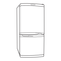
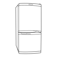
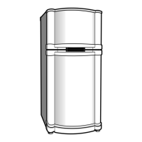
Provides detailed specifications for the LG GR-389 refrigerator model.
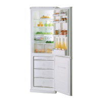
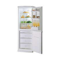
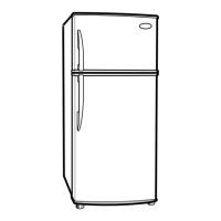
Provides detailed specifications for the LG GR-349 refrigerator model.
Diagram illustrating the location of various refrigerator components.
Important safety precautions to follow before reversing refrigerator doors.
Step-by-step guide on how to reverse the refrigerator door opening direction.
Steps to remove and disassemble the freezer door.
Instructions for removing and accessing the door switch.
Procedure for removing the refrigerator's internal lamp.
Steps to disassemble and remove the fan and its motor.
Details on removing and replacing the defrost control assembly.
Instructions for removing the damper control unit.
Procedure for replacing the sheath heater used for defrosting.
Explains compressor role, composition, and important usage precautions.
Details PTC-starter function, circuit, and notes for motor starting.
Defines OLP, its role in protecting the compressor motor from overcurrent.
Schematic diagram for refrigerator circuit 1.
Schematic diagram for refrigerator circuit 2.
Troubleshooting steps for compressor and related electrical components.
Diagnostic procedures for PTC starters and Over Load Protectors.
Identifies and troubleshoots other electrical parts like fans and heaters.
A chart to diagnose refrigerator complaints based on symptoms.
Diagnoses issues related to refrigerant leakage, clogging, and compression.
Explains basic refrigerator operation modes like Mid, Max, Min settings.
Details the quick freezing feature, its operation, and defrosting interaction.
Describes the energy-saving vacation mode and its operational parameters.
Explains the alarm triggered by the refrigerator door remaining open.
Describes the buzzer sound when display buttons are pressed.
Outlines the automatic defrosting cycle initiation and operation.
Specifies the sequence of operation for key electrical components like compressor and fan.
Details the self-test mode for diagnosing product troubles using error codes.
Explains how to perform test modes to check PCB and refrigerator functions.
Explains the electric power circuits for relay driving and MICOM supply.
Describes the oscillation circuit responsible for generating the clock signal for MICOM.
Explains how the MICOM resets to initial conditions upon power-on or failure.
Details the circuits for load operation, buzzer, and door opening detection.
Provides procedures to check buzzer operations for display buttons and door alarms.
Describes circuits for reading room, defrost, and freezer sensor temperatures.
Explains the circuit for testing switch inputs on the refrigerator.
Details resistance values and their effect on freezer temperature compensation.
Circuits for judging function key operation and lighting indication LEDs.
Table showing sensor resistance at different measured temperatures.
Diagram of the main Printed Wiring Board (PWB) with component layout.
Visual breakdown of refrigerator components with reference numbers.
A list of all replaceable parts with their corresponding numbers and descriptions.
Comprehensive list of replacement parts specific to model GR-349.
Comprehensive list of replacement parts specific to model GR-389.
| Door hinge | Right |
|---|---|
| Product color | White |
| Appliance placement | Freestanding |
| Door open alarm | Yes |
| Total gross capacity | 264 L |
| Annual energy consumption | 460 kWh |
| Freezer gross capacity | 86 L |
| Fridge net capacity | 178 L |
| Package weight | 74000 g |
| Depth | 626 mm |
|---|---|
| Width | 595 mm |
| Height | 1710 mm |
| Weight | 69000 g |