EasyManua.ls Logo

LG GR-559JPA User Manual

LG GR-559JPA
50 pages
To Next Page IconTo Next Page
Page #1 background imageLoading...
Page #1 background image
CAUTION
BEFORE SERVICING THE UNIT, READ THE "SAFETY
PRECAUTIONS" IN THIS MANUAL.
MODEL:GR-559JPA
REFRIGERATOR
SERVICE MANUAL
COLOR: SUPER WHITE
http://biz.lgservice.com
Ref. No.
GR-652JPA
Question and Answer IconNeed help?

Do you have a question about the LG GR-559JPA and is the answer not in the manual?

LG GR-559JPA Specifications

General IconGeneral
BrandLG
ModelGR-559JPA
CategoryRefrigerator
LanguageEnglish

Summary

SAFETY PRECAUTIONS

SERVICING PRECAUTIONS

Air Recharging in Compressor

Procedure for recharging refrigerant into the compressor system.

1. SPECIFICATIONS

2. PARTS IDENTIFICATION

2-1. FEATURE CHART

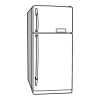
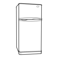
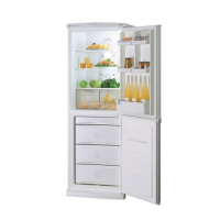
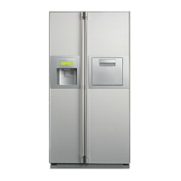
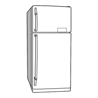
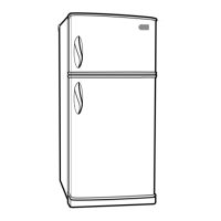
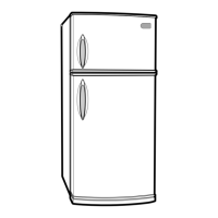
Diagram showing features and components of the refrigerator.

3. DISASSEMBLY

3-1 DOOR

Procedures for removing the freezer and refrigerator doors.

3-2 DOOR SWITCH

Steps to remove and disconnect the door switch.

3-3 FAN AND FAN MOTOR

Guide to disassembling the fan and fan motor assembly.

3-4 DEF' CONTROL ASSY

Details on removing the defrost control assembly.

3-5 LAMP

Instructions for replacing lamps in the freezer and refrigerator.

3-6 CONTROL BOX-R

Steps for accessing and removing the control box.

4. ADJUSTMENT

4-1 COMPRESSOR

Information about the compressor's role, composition, and usage notes.

4-2 PTC-STARTER

Details on the PTC starter's composition, role, and circuit.

4-3 OLP (OVER LOAD PROTECTOR)

5. CIRCUIT DIAGRAM

6. TROUBLESHOOTING

6-1 COMPRESSOR AND ELECTRIC COMPONENTS

Troubleshooting steps for compressor and related electric parts.

6-2 PTC AND OLP

6-3 ANOTHER ELECTRIC COMPONENTS

6-4 SERVICE DIAGNOSIS CHART

6-5 REFRIGERATING CYCLE

Leakage Detection

Methods to detect refrigerant leakage in the system.

General Control of Refrigerating Cycle

7. DESCRIPTION OF FUNCTION & CIRCUIT OF MICOM

7-1 FUNCTION

Overview of the refrigerator's main functions and operations.

7-2 PCB FUNCTION

Details on the Printed Circuit Board's functions and circuits.

7-3. RESISTANCE SPECIFICATION OF SENSOR

7-4. TRUBLE SHOOTING

7-5 MAIN PWB ASS'Y AND PARTS LIST

7-5-1 MAIN PWB ASS'Y

Diagram of the main Printed Circuit Board assembly.

7-5-2 REPLACEMENT PARTS LIST

7-5-3 PWB ASS'Y, DISPLAY AND PARTS LIST

7-6 PWB DIAGRAM

8. EXPLODED VIEW & REPLACEMENT PARTS LIST

8-1.

Diagram showing the exploded view of refrigerator parts.

Related product manuals