EasyManuals Logo

LG GR-A207CTBA User Manual

LG GR-A207CTBA
80 pages
To Next Page IconTo Next Page
To Previous Page IconTo Previous Page
Page #18 background imageLoading...
Page #18 background image
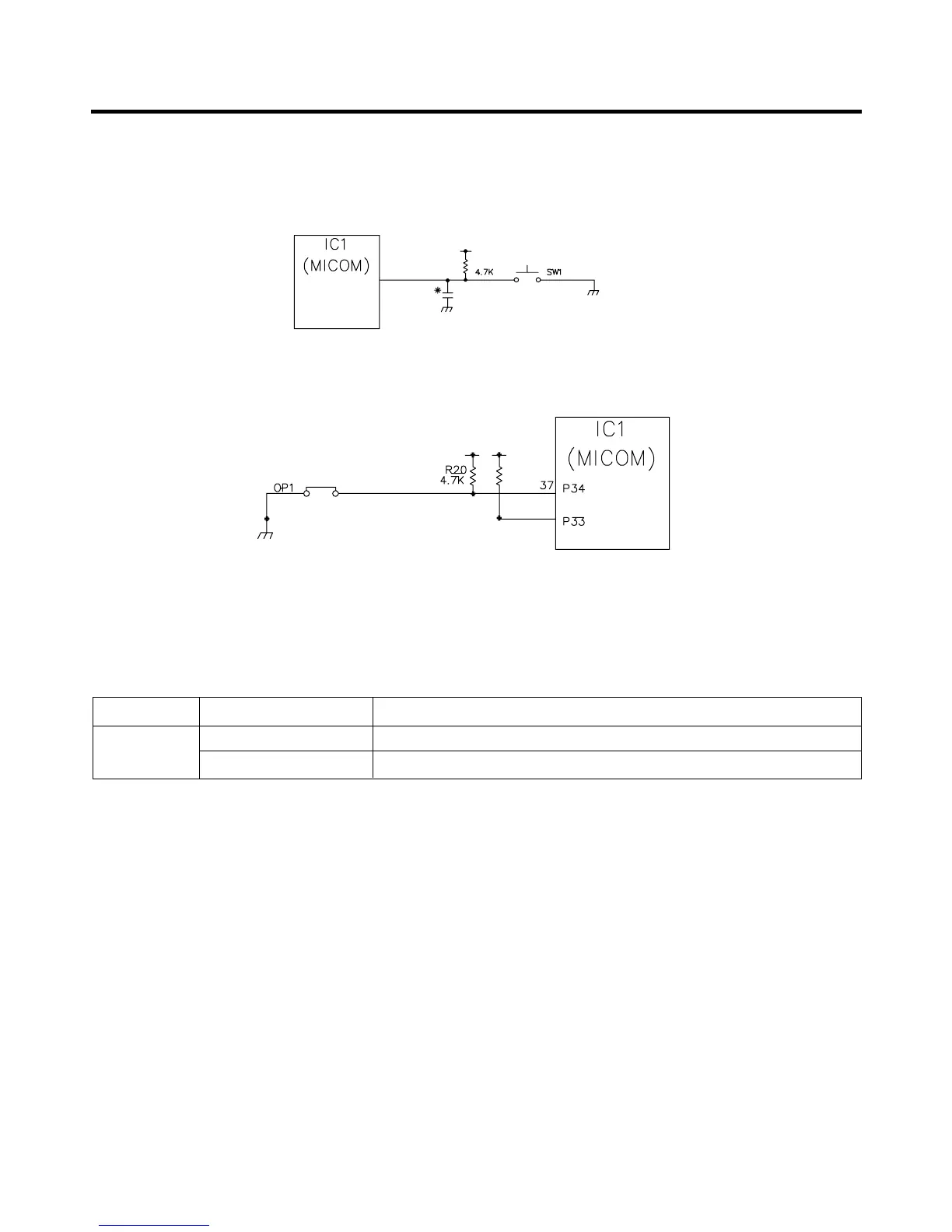
1-6. Switch entry circuit
The following circuits are entry circuits for sensing signal form test S/W, electronic single motor damper reed S/W for
examining refrigerator.
1) GR-A207
1-7. Option designation circuit (model separation function)
1) GR-A207
The above circuits are used for designating separation by model as option and notifying it to MICOM. Designation of option
by model and the application standards are as follows:
u These circuits are accurately pre-adjusted in shipment from factory and so you must not additionally add or remove
option.
EXPLATION FOR MICOM CIRCUIT
- 18 -
47
P46
R26
CC11
223
36
R21
4.7K
Separation Connection Status Application Standard
Connection MAGIC/ROOM
OP1
OUT NON-MAGIC/ROOM

Questions and Answers:

Question and Answer IconNeed help?

Do you have a question about the LG GR-A207CTBA and is the answer not in the manual?

LG GR-A207CTBA Specifications

General IconGeneral
BrandLG
ModelGR-A207CTBA
CategoryRefrigerator
LanguageEnglish

Related product manuals