42
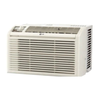
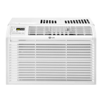
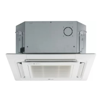
Multi F Ceiling Cassette Indoor Unit
Due to our policy of continuous product innovation, some specifications may change without notification.
©LG Electronics U.S.A., Inc., Englewood Cliffs, NJ. All rights reserved. “LG” is a registered trademark of LG Corp.
MA
TI
F
TI
ELECTRICAL WIRING
Indoor Unit Electrical Connections Procedure
Indoor Unit Terminal Block
1(L1 )2(L2)
GND
GND
GRN / YLW
BR
BL
RD
3
3 or S
S N L
BDU:
ODU:
Branch Distribution Unit Terminal Block or
Outdoor Unit Terminal Block
Figure 54: Typical Indoor Unit Terminal Block with Grounding Cable
(Actual Appearance May Vary).
Figure 53: Simplied View of Indoor Unit to Outdoor Unit / Branch
Distribution Unit Terminal Connections.
Ceiling cassette 4-way _ 19
Rubber Stopper
Cable
Conduit
Screws
Conduit Bracket
Using a Conduit
1. Remove the rubber stopper on the indoor unit. Pass the power
wiring / communications cable through the conduit, the conduit
mounting plate, and to / through the control panel of the indoor
unit.
2. Tighten the conduit and the conduit mounting plate together.
3. Connect the power wiring / communications cable to the indoor
unit terminal block.
4. Screw the conduit mounting plate to the indoor unit.
Figure 55: Using a Conduit.
If the distance between the outdoor unit and indoor unit is greater
than 131 feet, connect the power wiring and communications cable
separately (i.e., a conduit cannot be used).
Figure 56: PTVK430 Ventilation Kit.
PTVK430 Ventilation Kit
PTVK430 Ventilation Kit includes a flange for field-supplied ventilation pipe connection.
Easily connects at the four-way ceiling-cassette three (3) inch fresh air knockout hole.
Note:
 Loading...