44
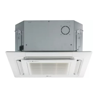
Multi F Ceiling Cassette Indoor Unit
Due to our policy of continuous product innovation, some specifications may change without notification.
©LG Electronics U.S.A., Inc., Englewood Cliffs, NJ. All rights reserved. “LG” is a registered trademark of LG Corp.
MA
TI
F
TI
ELECTRICAL WIRING
Additional screens can be accessed by tabs on the main screen.
Additional screens include the following:
1. Cycleview (Figure 60): Graphic of internal components including:
• Compressors showing actual speeds
• EEVs
• IDUs
• Temperature and pressure sensors
• Four-way reversing valve
2. Graph: Full screen graph of actual high and low pressures and high
and low pressure limits. A sliding bar enables user to go back in
time and view data.
3. Control FTN: Enables user to turn on IDUs in 1.8°F increments.
4. Useful Tab
• Unit Conversion: Converts metric values to imperial values.
• Actual inverter compressor speed
• Target inverter compressor speed
• Actual outdoor fan speed
• Target outdoor unit fan speed
• Actual superheat
• Target superheat
• Actual subcooler circuit superheat
• Target subcooler circuit superheat
• Main EEV position
• Subcooling EEV position
• Inverter compressor current transducer
value
• Outdoor air temperature
• Actual high pressure/saturation temperature
• Actual low pressure/saturation temperature
• Suction temperature
• Inverter compressor discharge temperature
• Front outdoor coil pipe temperature
• Back outdoor coil pipe temperature
• Liquid line pipe temperature
• Subcooler inlet temperature
• Subcooler outlet temperature
• Average indoor unit (IDU) pipe temperature
• Inverter compres-
sor operation
indicator light
• Liquid injection
valves’ operation
indicator lights
• Hot gas bypass
valve operation
indicator light
• Four-way revers-
ing valve operation
indicator light
• Pressure graph
showing actual
low pressure and high
pressure levels
• Error code display
• Operating mode indicator
• Target high pressure
• Target low pressure
• PCB (printed circuit board) version
• Software version
• Installer name
• Model number of IDUs
• Site name
• Total number of connected IDUs
• Communication indicators
• IDU capacity
• IDU operating mode
• IDU fan speed
• IDU EEV position
• IDU room temperature
• IDU inlet pipe temperature
• IDU outlet pipe temperature
• IDU error code
LG Monitoring View (LGMV) Diagnostic Software
LGMV software (PRCTSL1 and PRCTFE1) allows the service technician or commissioning agent to connect a computer USB port to the
outdoor unit’s main printed circuit board (PCB) using an accessory cable. The monitoring screen for LGMV allows the user to view the fol-
lowing real time data on one screen (Figure 59):
Figure 59: MV Real-time Data Screen.
Figure 60: MV Cycleview.
Note:
Images on these pages are examples of LGMV screenshots. Actual images
may differ depending on the version of the software and the unit installed.
Self Diagnosis Functions
 Loading...