Do you have a question about the LG LFX25961 Series and is the answer not in the manual?
Detailed specifications including dimensions, net weight, cooling system, and electrical components.
Identification of key interior parts like adjustable shelving, door bins, and ice storage.
Step-by-step guide for disassembling and removing the refrigerator doors.
Procedures for door removal, gasket replacement, and door alignment.
Instructions for removing the evaporator fan and its motor.
Steps to remove the defrost control assembly, including sensor and fuse.
Procedures for accessing and removing the multi duct, main PWB, and dispenser components.
Guidance on disassembling the icemaker assembly and auger motor cover.
Instructions for removing and inserting the door ice bin and pullout drawer.
Methods for disassembling the water valve and fan motor assemblies.
Instructions for the operation and removal of the pull-out drawer.
Information on the compressor's role, composition, and usage precautions.
Details on PTC-starter composition, role, circuit diagram, and OLP function.
Definition and role of the Overload Protector (OLP) and its relation to the compressor.
Procedure for removing the cover associated with the PTC starter.
Comprehensive wiring diagram for the refrigerator's main control and power systems.
Troubleshooting flowcharts for compressor and related electrical components.
Diagnosis and solutions for issues with fan motors and defrosting systems.
A structured chart for diagnosing common refrigerator complaints.
Chart detailing causes and states related to refrigeration cycle problems.
Diagnostic flowchart for 'Not Cooling' complaints related to the sealed system.
Explanation of the icemaker's operational principles and modes.
Details on icemaking, harvest, fill modes, and function test procedures.
Information on error codes and defect diagnosis for the icemaker system.
Overview of refrigerator functions, temperature settings, and display modes.
Details on Ice Plus function, dispenser usage, and fan motor control.
Explanation of the defrosting cycle and defect diagnosis system.
List of error codes, detection categories, generation factors, and remarks.
Instructions for operating the product in test mode for diagnostics.
Overview of the PCB functions, including the power circuit and voltage specifications.
Description of temperature sensor circuits, check points, and voltage readings.
Table detailing sensor resistance values at various temperatures.
Circuit diagrams for the stepping motor damper and dispenser drive.
Troubleshooting guide for common issues like power, cooling, and temperature problems.
Exploded view and parts list for the main cabinet and case components.
Exploded view and parts list for the freezer compartment components.
Exploded view and parts list for the refrigerator compartment components.
Exploded view and parts list for various door components and bins.
Exploded views and parts lists for the dispenser and ice bank assemblies.
Exploded view and parts list for the ice maker system components.
Exploded view and parts list for the ice bank components.
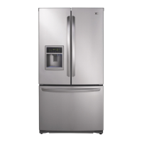
| Type | French Door |
|---|---|
| Ice Maker | Yes |
| Water Dispenser | Yes |
| Energy Star Certified | Yes |
| Door Alarm | Yes |
| Adjustable Shelves | Yes |
| Interior Lighting | LED |
| Color | Stainless Steel |