Do you have a question about the LG LH-T7652SB and is the answer not in the manual?
Guidelines for safe handling, storage, and repair of audio components, especially the pick-up.
Specific precautions for CD player repairs, focusing on static electricity and component handling.
Detailed instructions to prevent damage from electrostatic discharge to sensitive electronic components.
Procedures and information for accessing and modifying EEPROM settings via the remote control.
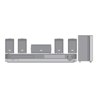
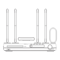
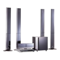
Technical details and performance characteristics of the DVD/CD Receiver and its speakers.
Step-by-step flowchart for diagnosing and resolving audio output issues in the unit.
Illustrates the electrical connections between various internal components and external interfaces.
High-level overview of the system's functional blocks and their interconnections.
Detailed schematic diagrams for the power supply and other electronic circuits within the unit.
Visual layouts of the main, SMPS, key, and timer printed circuit boards for component identification.
Flowcharts for diagnosing operational issues, including system flow and test/debug procedures.
Schematic diagrams detailing the MPEG, DSP, and AMP circuits for DVD and audio amplification.
Visual layouts of the DSP and AMP printed circuit boards for component identification and placement.
Exploded view showing the assembly of the main chassis, front panel, and internal frame components.
Detailed exploded view of the disc loading and transport mechanism, including part numbers.
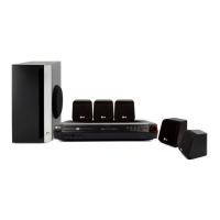
Illustration of the various accessories included in the product packaging, such as remote, cables, and manual.
Exploded view and part identification for the central speaker unit.
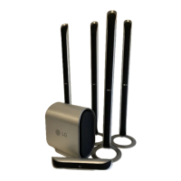
Exploded view and part identification for the front and rear satellite speaker units.
Exploded view and part identification for the passive subwoofer speaker unit.