Do you have a question about the LG LMV1813ST and is the answer not in the manual?
Table detailing switch modes and conditions for microwave operation.
Safety precautions regarding exposure to microwave energy during service.
Guidelines for safe and proper installation of the microwave oven.
Essential steps for ensuring the unit is safely grounded to prevent electric shock.
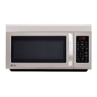
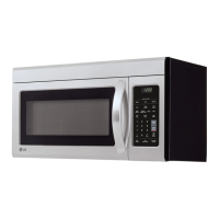
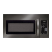
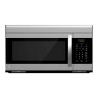
Overview of the microwave's control panel buttons and display functions.
Detailed explanation of each function and button on the control panel.
Schematic diagram illustrating the electrical connections within the microwave.
Matrix showing the relationship between keypad inputs and oven functions.
Important preliminary information and precautions for service technicians.
Critical safety warnings and procedures to follow before and during servicing.
Summary of basic checks for diagnosing common microwave operational issues.
Specific troubleshooting steps for diagnosing and resolving various operational faults.
Diagnostic steps for addressing issues where the keypad is not functioning correctly.
Troubleshooting guide for situations where the microwave does not heat or cook food.
Steps to diagnose and resolve problems with the turntable motor not operating.
Troubleshooting steps for when the microwave unexpectedly turns on by itself.
Safety considerations and necessary equipment for performing microwave leakage tests.
Procedure for measuring microwave energy leakage using specialized equipment.
Guidelines for measuring leakage with and without the outer case, and record keeping.
Details on the door interlock mechanism, its adjustment, and related checks.
Procedures for testing latch sequence, energy leakage, and switch continuity.
Safety notes and general procedures for testing microwave components.
Detailed tests for capacitors, diodes, motors, sensors, and keypads.
Critical notes and steps for removing the power and control circuit board.
Procedures for handling FPC connectors and removing the outer case.
Instructions for disassembling and removing the outer casing of the microwave oven.
Steps for safely removing the door interlock switches for inspection or replacement.
Procedures for removing the magnetron and stirrer fan assembly.
Instructions for removing the door, ventilation motor, and turntable motor.
Steps for removing and replacing the humidity sensor unit.
Exploded view diagram showing the assembly of door components.
Exploded view diagram illustrating the various controller assembly parts.
Exploded view diagram detailing components within the oven cavity.
Exploded view diagram showing the components of the latch board assembly.
Exploded view diagram illustrating internal components of the microwave.
Exploded view diagram showing additional interior parts of the microwave.
Exploded view diagram detailing parts used for microwave installation.
| Type | Over-the-Range |
|---|---|
| Capacity | 1.8 cu. ft. |
| Power | 1000 Watts |
| Control Type | Touch |
| Ventilation | Yes |
| Turntable | Yes |
| Sensor Cooking | Yes |
| Color | Stainless Steel |
| Convection Cooking | No |
| Grill | No |
| Child Lock | Yes |
| Auto Defrost | Yes |
| Number of Power Levels | 10 |
| Turntable Diameter | 14.2 inches |
| Exterior Dimensions | 29.88" x 15.38" x 15.5" |