EasyManua.ls Logo

LG LS-F1260HL User Manual

LG LS-F1260HL
67 pages
To Next Page IconTo Next Page
Page #1 background imageLoading...
Page #1 background image
Room Air Conditioner
SVC MANUAL(Exploded View)
CAUTION
Before Servicing the unit, read the safety precautions in General SVC manual.
Only for authorized service personnel.
Internal Use Only
http://biz.lgservice.com
MODEL : LS-E0960CL / CM / CN / CD / CS
LS-E0960HL / HM / HN / HD / HS
LS-F1260CL / CM / CN / CD / CS
LS-F1260HL / HM / HN / HD / HS
LS-J0760CL / CM / CN / CD / CS
LS-J0760HL / HM / HN / HD / HS
LS-J0960CL / CM / CN / CD / CS
LS-J0960HL / HM / HN / HD / HS

Questions and Answers:

LG LS-F1260HL Specifications

General IconGeneral
BrandLG
ModelLS-F1260HL
CategoryAir Conditioner
LanguageEnglish

Summary

Dimensions

Indoor Unit Dimensions

Details dimensions for the indoor unit, including width, height, and depth.

Outdoor Unit Dimensions

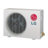
Details dimensions for the outdoor units of various models.

Refrigeration Cycle Diagram

Wiring Diagrams

Indoor Unit Wiring

Illustrates the wiring connections for the indoor unit.

Outdoor Unit Wiring (Cooling Only)

Shows wiring for outdoor units in cooling-only models.

Indoor Unit Wiring (Cooling & Heating)

Wiring diagram for indoor unit (cooling/heating).

Outdoor Unit Wiring (Cooling & Heating)

Details wiring for outdoor units in cooling and heating models.

Operation Details

Cooling and Dehumidification Mode Details

Details on cooling and healthy dehumidification operation modes.

Heating and Defrost Mode Details

Details on heating and defrost operation modes.

Display Functions

Indicator Descriptions

Details operation, sleep, timer, and compressor indicators for different models.

Self-Diagnosis Function

Thermistor Error Indicator

Describes error indication for open or shorted thermistor sensors.

Installation Procedures

Location Selection Guidelines

Guidelines for choosing optimal locations for indoor and outdoor units.

Indoor Unit Installation Steps

Steps for mounting the indoor unit, including plate and piping preparation.

Indoor Unit Piping and Connections

Details on preparing and connecting indoor unit piping, drain hose, and cables.

Outdoor Unit Piping and Cable Connections

Steps for connecting piping and cables to the outdoor unit.

Operation Modes and Controls

Cooling Model Remote Control Functions

Details the buttons and functions of the remote control for cooling models.

Heat Pump Model Remote Control Functions

Details the buttons and functions of the remote control for heat pump models.

Indoor Unit Disassembly

Disassembly Steps for Indoor Unit Components

Instructions for removing the grille, control box, fan, and evaporator.

Valve Operations and Refrigerant Management

2-Way and 3-Way Valve Operation Guide

Details valve positions for shipping, purging, operation, and servicing.

Pumping Down, Evacuation, and Gas Charging

Procedures for managing refrigerant through pumping down, evacuation, and charging.

Troubleshooting Guides

Cycle Troubleshooting Analysis

Guides troubleshooting by analyzing temperature differences and operating current.

Electronic Parts Troubleshooting

Diagnosing issues with electronic components and PCB boards.

Operation and Component Troubleshooting

Diagnosing issues with remote control, fan, louver, heating, and compressor operations.

Electronic Control Device and Schematics

Main PCB Assembly Details

Diagram and parts list for the main PCB assembly.

Schematic Diagrams

Circuit diagrams for cooling-only and heat pump models.

Exploded Views

Indoor Unit Exploded Views

Exploded views of various indoor unit models.

Outdoor Unit Exploded Views

Exploded views of various outdoor unit models.

Related product manuals