

E
Eric BrockJul 31, 2025
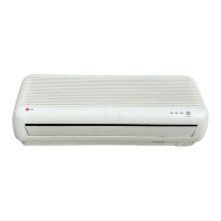
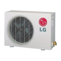
Why doesn't the high pressure rise quickly at the beginning of operation of my LG LS-E0960CL Air Conditioner?
- CchavezedwinAug 1, 2025
If the high pressure in your LG Air Conditioner doesn't rise quickly at the start, it could be due to an excessive amount of refrigerant. Unfortunately, the manual does not provide a specific solution for this problem.