EasyManua.ls Logo

LG LS-K2460CL User Manual

LG LS-K2460CL
79 pages
To Next Page IconTo Next Page
Page #1 background imageLoading...
Page #1 background image
Room Air Conditioner
SERVICE MANUAL
MODEL : LS-K1820CL/CM/CN/HL/HM/HN
LS-K1822CL/CM/CN/HL/HM/HN
LS-K1860CL/CM/CN/HL/HM/HN
LS-K1861CL/CM/CN/HL/HM/HN
LS-K1862CL/CM/CN/HL/HM/HN
LS-K1865CL/CM/CN/HL/HM/HN
LS-K1866CL/CM/CN/HL/HM/HN
LS-K2460CL/CM/CN/HL/HM/HN
LS-K2462CL/CM/CN/HL/HM/HN
LS-K2420CL/CM/CN/HL/HM/HN
LS-K2422CL/CM/CN/HL/HM/HN
LS-K2621CL/CM/CN/HL/HM/HN
LS-K2661CL/CM/CN/HL/HM/HN
LS-K2662CL/CM/CN/HL/HM/HN
LS-K1863DL

Other manuals for LG LS-K2460CL

Questions and Answers:

LG LS-K2460CL Specifications

General IconGeneral
TypeSplit System
Cooling Capacity24000 BTU/h
RefrigerantR410A
Compressor TypeRotary
Power Supply220-240V, 50Hz
Operating Temperature (Cooling)18-43°C
Air Flow Rate12.5 m³/min

Summary

Functions

Indoor Unit Functions

Details the various functions and operations of the indoor unit.

Dimensions

Indoor Unit Dimensions

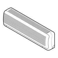
Provides dimensional details and diagrams for the indoor unit.

Outdoor Unit Dimensions

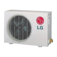
Provides dimensional details and diagrams for the outdoor unit.

Refrigeration Cycle Diagram

Cooling Only Models Cycle

Illustrates the refrigeration cycle for cooling-only models.

Cooling & Heating Models Cycle

Illustrates the refrigeration cycle for cooling and heating models.

Pipe length and the elevation

Wiring Diagram

Indoor Unit Wiring Diagrams

Details the wiring diagrams for various indoor unit models.

Outdoor Unit Wiring Diagrams

Details the wiring diagrams for various outdoor unit models.

Operation Details

Main Unit Functions & Indicators

Overview of main unit operations, indicators, and modes.

Heating & Defrost Control

Details heating operation and defrost control methods.

Fuzzy Operation Modes

Describes fuzzy operation logic for C/O and H/P models.

Timer and Special Operations

Details timer operations, auto-restart, and chaos modes.

Forced & Test Operation

Explains forced and test operation modes.

Remote Control & Safety Operations

Covers remote control, frosting protection, self-diagnosis, and air cleaner.

Display Function

Heating Model Displays

Details display indicators for heating mode.

Cooling Model Displays

Details display indicators for cooling mode.

Self-diagnosis Function

Thermistor Error Handling

Describes error indication for thermistor issues.

Evaporator Frosting Protection

Explains protection against evaporator pipe frosting.

Installation

Unit Location Selection

Covers the selection of location for indoor and outdoor units.

Piping Requirements

Details pipe length and elevation requirements.

Installation Plate & Hole Drilling

Instructions for mounting the plate and drilling the wall.

Flaring Work and Connection of Piping

Pipe Flaring Procedures

Steps for performing correct flaring work on pipes.

Indoor Unit Piping Connection

Steps for connecting piping to the indoor unit.

Outdoor Unit Piping Connection

Steps for connecting pipes to the outdoor unit.

Connecting the Cable Between Indoor Unit and Outdoor Unit

Indoor Unit Cable Connection

Instructions for connecting cables to the indoor unit.

Outdoor Unit Cable Connection

Instructions for connecting cables to the outdoor unit.

Checking the Drainage and Forming the Pipings

Drainage Check Procedures

Procedures to check the drainage system of the indoor unit.

Piping Formation and Routing

Steps for forming and securing the piping.

Drain Piping Guidelines

Guidelines for drain piping to ensure proper flow.

Air Purging

Purging Importance and Methods

Explains the importance of air purging and its effects.

Vacuum Pump Evacuation

Detailed steps for air purging using a vacuum pump.

System Evacuation and Finishing

Procedure for evacuating the system and final steps.

Pumping down

Pumping Down Procedure

Step-by-step procedure for pumping down the system.

Re-air purging (Re-installation)

Re-air Purging Procedure

Procedure for re-purging the air after re-installation.

Balance refrigerant of the 2-way, 3-way valves

Refrigerant Balancing Procedure

Steps to balance refrigerant levels in valves.

Evacuation

Evacuation Procedure

Procedure for evacuating the system to remove all refrigerant.

Gas Charging

Gas Charging Procedure

Steps for charging the system with refrigerant after evacuation.

Cycle Troubleshooting Guide

Trouble Analysis

Analysis of common operational issues based on temperature and current.

Electronic Parts Troubleshooting Guide

Product Not Operating

Troubleshooting steps when the product does not operate.

Remote Control Issues

Troubleshooting steps when the remote controller does not work.

Compressor/Fan Operation Failure

Troubleshooting steps when the compressor or outdoor fan fails to operate.

Indoor Fan Operation Failure

Troubleshooting steps when the indoor fan does not operate.

Vertical Louver & Heating Failure

Troubleshooting steps for louver and heating function failures.

Electronic Control Device

Main P.W.B Assembly

Information on the main Printed Wiring Board Assembly.

Display Assembly Details

Details about the display assembly.

Schematic Diagram

Cooling Only Series Schematics

Schematic diagram for cooling-only models.

Heat Pump Series Schematics

Schematic diagram for heat pump models.

Exploded View & Replacement Parts List

Indoor Unit Parts List

Exploded view and parts list for the indoor unit.

Outdoor Unit Exploded View

Exploded view of the outdoor unit.

Related product manuals