EasyManua.ls Logo

LG LS-K2430HL - User Manual

LG LS-K2430HL
73 pages
To Next Page IconTo Next Page
Loading...
SERVICE MANUAL
Room Air Conditioner
MODEL : LS-J0910CL / HL
LS-L1210CL / HL
LS-K1830CL / HL
LS-K2430CL / HL

Questions and Answers:

LG LS-K2430HL Specifications

General IconGeneral
TypeSplit System
Cooling Capacity24000 BTU/h
Compressor TypeRotary
Power Supply220-240V, 50Hz
Airflow Rate12 m³/min
Operating Temperature (Cooling)18°C to 43°C
Operating Temperature (Heating)24°C

Summary

Functions

Indoor Unit Functions

Details of the indoor unit's operational modes and features.

Remote Controller Functions

Remote Controller Operations

Explanation of buttons and operations for the remote control unit.

Dimensions and Specifications

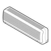
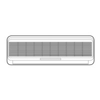
Indoor Unit Dimensions

Measurements and diagrams for the indoor air conditioning unit.

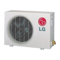
Outdoor Unit Dimensions

Measurements and diagrams for the outdoor air conditioning unit.

Refrigeration Cycle Diagrams

Cooling Only Models Cycle

Diagram illustrating the refrigerant flow for cooling-only operation.

Cooling & Heating Models Cycle

Diagram showing refrigerant flow for cooling and heating modes.

Wiring Diagrams

Indoor Unit Wiring

Electrical schematic for the indoor unit's components and connections.

Outdoor Unit Wiring

Electrical schematic for the outdoor unit's components and connections.

Cooling & Heating Models Wiring

Wiring diagrams specific to cooling and heating operation modes.

Operation Details and Modes

Main Control Functions

Explains time delay, chaos swing, and cooling operation modes.

Auto Operation Modes

Details automatic operation for cooling, dehumidification, and heating.

Special Operation Modes

Covers heating mode, hot-start, and sleep mode operations.

Forced and Auto Restart Operations

Procedures for forced operation and automatic restart after power loss.

Display and Diagnostic Functions

Display Indicators and Sounds

Explains LED indicators, buzzer sounds, and display functions.

Self-diagnosis Function

Guide to identifying operational issues through LED blink codes.

Installation Procedures

Safety, Parts, and Preparation

Safety warnings, provided parts, and initial preparation steps for installation.

Unit Placement and Mounting

Guidelines for selecting locations and mounting indoor/outdoor units, including piping considerations.

Piping and Tubing Connections

Detailed instructions for flaring, connecting pipes, and tubing for both indoor and outdoor units.

Electrical Wiring and Cable Connection

Steps for connecting indoor/outdoor electrical cables and wiring methods.

Drainage, Piping, and Air Purging

Drainage and Piping Formation

Procedures for checking drainage and forming refrigerant piping.

Air Purging with Vacuum Pump

Steps for leak testing, evacuation, and final finishing of the refrigerant system.

Test Running and Pump Down Procedures

Test Running Procedure

Steps to verify system operation and refrigerant charge after installation.

Pump Down Procedure

Method for collecting refrigerant when relocating or servicing the unit.

Remote Controller Usage

Cooling Model Remote

Functions and layout of the remote controller for cooling models.

Heat Pump Model Remote

Functions and layout of the remote controller for heat pump models.

Indoor Unit Disassembly Guide

9 K, 12 K Models Disassembly

Step-by-step guide to disassembling the indoor unit for 9K and 12K models.

18 K, 24 K Models Disassembly

Step-by-step guide to disassembling the indoor unit for 18K and 24K models.

Troubleshooting Guide

Trouble Analysis and Diagnosis

Methods for analyzing operational issues based on temperature, pressure, and current.

Product Operation Failures

Troubleshooting steps for general operation, remote control, and component drive issues.

Fan, Louver, and Communication Errors

Diagnosing issues with indoor fan, vertical louver, and communication between units.

Connection Error Phenomena

Phenomena and indicators related to indoor and outdoor unit connection errors.

Connector Voltage Specifications

Connector Voltage Specifications

Table detailing voltage values for various connectors based on fan speed.

Electronic Control Components

Indoor Unit PWB Assembly

Diagram and parts list for the main printed circuit board of the indoor unit.

Outdoor Unit PWB Assembly

Diagram and parts list for the main printed circuit board of the outdoor unit.

Display PWB Assembly

Diagram for the display printed circuit board assembly.

Schematic Diagrams

Indoor Unit Schematic

Detailed electrical schematic of the indoor unit's circuitry.

Outdoor Unit Schematic

Detailed electrical schematic of the outdoor unit's circuitry.

Exploded Views and Parts Lists

Indoor Unit Exploded Views & Parts

Visual breakdown and component lists for 9K, 12K, 18K, 24K indoor units.

Outdoor Unit Exploded Views & Parts

Visual breakdown and component lists for 9K, 12K, 18K, 24K outdoor units.

Related product manuals