R
rosscarpenterAug 7, 2025
Why is my LG LS-J0761CL leaking refrigerant?
- TTracy PayneAug 8, 2025
If your LG Air Conditioner experiences refrigerant leakage, it could stem from a clog in the refrigeration cycle or a defective compressor.
Why is my LG LS-J0761CL leaking refrigerant?
If your LG Air Conditioner experiences refrigerant leakage, it could stem from a clog in the refrigeration cycle or a defective compressor.
Why doesn't the high pressure rise quickly at the beginning of operation in my LG LS-J0761CL?
If your LG Air Conditioner's high pressure doesn't rise quickly at the start, it might be due to an excessive amount of refrigerant.
What causes low current in my LG LS-J0761CL Air Conditioner?
If the current is low in your LG Air Conditioner, this could be caused by a defective compressor or a defective 4-way reverse valve.
Details on operation, sensing, control, and indicators for the indoor unit.
Operation ON/OFF, Mode Selection, Fan Speed, Temp Settings.
Setting ON/OFF Timers, Sleep Mode Auto operation.
Airflow Direction, Jet Cool, Plasma/Ion, Horizontal Airflow.
Specifies cooling/heating capacity, air circulation, and noise levels.
Input power, motor output, dimensions, weight, and refrigerant type.
Physical measurements (W, H, D) and piping hole details for the indoor unit.
Physical measurements (W, H, D, L1-L5) for cooling-only models.
Physical measurements (W, H, D, L1-L5) for heat pump models.
Illustrates refrigerant flow for cooling and heating modes.
Details pipe diameter, max length, and elevation limits.
Wiring schematic for the indoor unit.
Wiring schematic for the outdoor unit.
Wiring for indoor units in cooling/heating models.
Wiring for outdoor units in cooling/heating models.
Explanation of indicators and Cooling/Dehumidification modes.
Heating mode logic and defrost control procedures.
Fuzzy logic for Cooling, Heat Pump, and Dehumidification modes.
On-Timer, Off-Timer, and Sleep Timer operations.
Sleep, Chaos Swing, Natural Wind, Jet Cool, Auto Restart, Forced Operation.
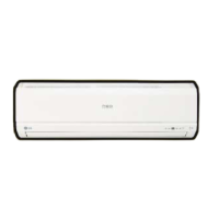
Guidelines for choosing the best location for the indoor unit.
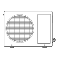
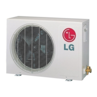
Guidelines for selecting a suitable location for the outdoor unit.
Mounting the installation plate and drilling for piping.
Steps for cutting pipes, removing burrs, and flaring ends.
Protecting flared pipe ends from dust or damages.
Guiding drain hose and indoor tubing through the wall.
Connecting indoor unit tubing to pipes and securing with insulation.
Hooking the indoor unit onto the installation plate and securing cables.
Routing and connecting pipes for left rear installation.
Bundling drain hose, piping, and cables together.
Aligning and tightening flare nuts for outdoor unit connections.
Safety and wiring guidelines for power connection.
Connecting wires to terminals for cooling-only and heat pump models.
Details on power cord and connecting cable types and lengths.
Verifying proper water flow from the evaporator.
Connecting wires to the indoor unit's control board.
Securing the front grille to the indoor unit chassis.
Piping installation when outdoor unit is below indoor unit.
Piping installation with a trap when outdoor unit is above indoor unit.
Detailed steps for purging air from the system using valves.
Using a manifold gauge to check for gas leaks.
Max pipe length, elevation, standard length, and additional refrigerant.
Guidelines for installing oil traps based on pipe length.
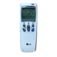
Connecting power supply and preparing the remote controller.
Anchoring the outdoor unit and vibration considerations.
Measuring air temperature difference to check performance.
Steps to remove the front grille, sensors, motors, and PCB.
Removing the control box, discharge grille, and evaporator assembly.
Removing the cross-flow fan and fan motor.
Steps for removing the grille on specific models.
Removing internal parts for specific models.
Removing control box and evaporator for specific models.
Removing cross-flow fan and motor for specific models.
Explains valve positions for shipping, operation, and servicing.
Steps to transfer refrigerant to the outdoor unit.
Using a vacuum pump to remove air and moisture from the system.
Adding refrigerant to the system after evacuation.
Troubleshooting based on intake/discharge air temp and operating current.
Diagnosing issues using suction pressure and temperature comparisons.
Troubleshooting steps when the unit does not operate at all.
Checking voltages and components on the PCB.
Diagnosing issues when the remote control is unresponsive.
Troubleshooting steps for compressor and outdoor fan not driving.
Steps to diagnose and fix indoor fan non-operation.
Diagnosing issues with the vertical louver movement.
Troubleshooting steps for when the heating mode fails.
Schematic of the main printed circuit board assembly.
Detailed electrical schematic for heat pump models.
Detailed electrical schematic for cooling-only models.
Visual breakdown of indoor unit components with part numbers.
List of replacement parts for indoor cooling units.
List of replacement parts for indoor heat pump units.
Visual breakdown of cooling outdoor unit components.
List of replacement parts for cooling outdoor models.
List of replacement parts for outdoor heat pump models.
| Brand | LG |
|---|---|
| Model | LS-J0761CL |
| Category | Air Conditioner |
| Language | English |