P
pfisherAug 7, 2025
Why is my LG LS-J0762HL leaking refrigerant?
- DDeborah HernandezAug 8, 2025
If your LG Air Conditioner experiences refrigerant leakage, it could stem from a clog in the refrigeration cycle or a defective compressor.
Why is my LG LS-J0762HL leaking refrigerant?
If your LG Air Conditioner experiences refrigerant leakage, it could stem from a clog in the refrigeration cycle or a defective compressor.
Why doesn't the high pressure rise quickly at the beginning of operation in my LG Air Conditioner?
If your LG Air Conditioner's high pressure doesn't rise quickly at the start, it might be due to an excessive amount of refrigerant.
What causes low current in my LG LS-J0762HL?
If the current is low in your LG Air Conditioner, this could be caused by a defective compressor or a defective 4-way reverse valve.
Diagrams and specifications for indoor unit dimensions.
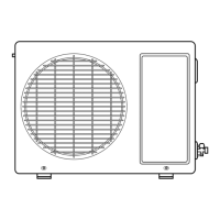
Diagrams and specifications for outdoor unit dimensions.
Wiring diagrams for cooling-only models.
Wiring diagrams for cooling and heating models.
Details on Cooling, Dehumidification, and Heating operations.
Explanation of fuzzy logic, airflow, timers, and special operating modes.
Indicator functions for heating and cooling modes.
Procedure for identifying thermistor errors via indicators.
Guidelines for selecting optimal locations and mounting the indoor unit.
Steps for preparing, connecting, and securing piping and cables.
Connecting pipes and cables to the outdoor unit with precautions.
Process for purging air and checking for gas leaks.
Steps for evacuating and charging the refrigeration system.
Connecting power, setting remote, and evaluating performance.
Steps for removing indoor unit grille, fan, and other components.
Analyzing temperature differences and operating currents for troubleshooting.
Troubleshooting steps for product and component failures.
Diagrams of the main circuit boards and display assembly.
Electrical schematic for heat pump series models.
Electrical schematic for cooling-only series models.
Exploded view and parts list for indoor units.
Components and parts list for outdoor units.
| Cooling Capacity | 7000 BTU/h |
|---|---|
| Power Supply | 220-240V, 50Hz |
| Refrigerant | R410A |
| Type | Split System |
| Heating Capacity | 7500 BTU/h |
| Power Consumption (Cooling) | 700W |
| Power Consumption (Heating) | 680 W |
| Operating Temperature (Cooling) | 18°C to 43°C |
| Operating Temperature (Heating) | -7°C to 24°C |