D
Dawn CarterAug 7, 2025
Why is my LG LS-J0763EL leaking refrigerant?
- SSarah FarrellAug 8, 2025
If your LG Air Conditioner experiences refrigerant leakage, it could stem from a clog in the refrigeration cycle or a defective compressor.
Why is my LG LS-J0763EL leaking refrigerant?
If your LG Air Conditioner experiences refrigerant leakage, it could stem from a clog in the refrigeration cycle or a defective compressor.
Why doesn't the high pressure rise quickly at the beginning of operation in my LG Air Conditioner?
If your LG Air Conditioner's high pressure doesn't rise quickly at the start, it might be due to an excessive amount of refrigerant.
What causes low current in my LG Air Conditioner?
If the current is low in your LG Air Conditioner, this could be caused by a defective compressor or a defective 4-way reverse valve.
Important safety warnings before servicing the unit.
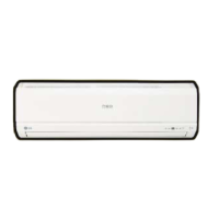
Remote operation, temperature sensing, fan speed, and indicators.
Sleep, Natural Air, Defrost, and Hot-start modes.
Mode selection, fan speed, and temperature settings.
Setting timers and sleep mode for operation.
Adjusting horizontal and vertical airflow.
Cooling capacity, moisture removal, energy efficiency.
Dimensions, weight, power source, and refrigerant.
Detailed dimensions (W x H x D) for indoor units.
Diagrams showing pipe routing on the wall.
Detailed dimensions for outdoor cooling units.
Detailed dimensions for outdoor heat pump units.
Diagram showing refrigerant flow and key parts.
Specifications for pipe size, length, and maximum elevation.
Electrical connections for the indoor unit.
Electrical connections for the outdoor unit.
Multiple wiring schematics for indoor units.
Multiple wiring schematics for outdoor units.
Explains the meaning of unit display elements and LEDs.
How the unit operates in cooling and dehumidification modes.
How the unit operates in heating mode, including temp control.
Procedure for defrosting to prevent ice buildup.
Details on Fuzzy logic for Cooling, Heating, and Dehumidification.
How to select fan speed via remote control.
Setting On-Timer and Off-Timer operations.
Adjusting operation for sleep comfort.
Chaos Swing and Natural Wind modes for airflow.
High-speed cooling and auto-resume after power loss.
Manual override modes for C/O and H/P units.
Frost protection mechanism and buzzer feedback.
Details on the air cleaner function.
Indicators for Heating and Cooling mode operations.
How errors related to temperature sensors are indicated.
Guidelines for choosing the best location for the indoor unit.
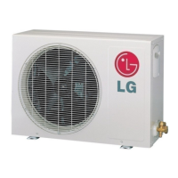
Guidelines for choosing the best location for the outdoor unit.
Steps for securely mounting the indoor unit's bracket.
Procedure for creating holes for piping and wiring.
Instructions for cutting, reaming, and flaring pipes.
Protecting the flared pipe ends.
Guiding the drain hose and refrigerant lines.
Details on connecting indoor and outdoor pipes with torque specs.
Shaping and bundling pipes, cables, and hoses.
Attaching the indoor unit to the installation plate.
Guiding the drain hose and refrigerant lines for left piping.
Details on connecting indoor and outdoor pipes with torque specs.
Insulating the connecting portions of the piping.
Securing the indoor unit onto the mounting bracket.
Finalizing pipe connections to the outdoor unit with torque.
Important electrical safety and installation guidelines.
Wiring differences for cooling-only and heat pump models.
Requirements for power supply and connecting cables.
Checking proper water drainage from the indoor unit.
Wiring the indoor unit based on outdoor unit connections.
Reassembling the front grille after installation.
Routing and securing piping for indoor unit installation.
Piping setup for outdoor units below or above indoor units.
Removing air and moisture from the refrigeration system.
Verifying the system for leaks after air purging.
Using gauges to check for leaks and pressure integrity.
Allowed pipe lengths and elevation differences.
How to calculate extra refrigerant for longer pipes.
Connecting power and remote controller for test operation.
Measuring temperature differences for proper operation.
Mode, fan speed, temperature, and timer controls.
Sleep mode and airflow direction adjustments.
Mode, fan speed, temperature, and timer controls for H/P.
Sleep mode and airflow direction adjustments for H/P.
Steps to detach the front grille assembly.
Steps to access sensors, motors, and PCB.
Detaching the main electronic control housing.
Steps to remove the air discharge grille.
Detaching the evaporator core.
Steps to remove the fan motor and fan assembly.
Detaching grille and control cover for specific models.
Steps to access internal parts for specific models.
Detaching control box and discharge grille for specific models.
Detaching evaporator and fan assembly for specific models.
Table detailing valve positions for shipping, purging, operation, etc.
Detailed guide for purging the refrigeration system.
Steps for transferring refrigerant to the outdoor unit.
Steps for purging air during re-installation.
Steps to balance refrigerant and check for leaks.
Steps for creating a vacuum in the system.
Steps for charging the system with refrigerant.
Diagnosing issues based on temperature and current readings.
Identifying causes of trouble from pressure and temperature data.
Troubleshooting steps when the product is completely non-functional.
Checking voltages and components on the PCB.
Troubleshooting if the remote control is unresponsive.
Diagnosing why the compressor or outdoor fan won't start.
Steps to diagnose indoor fan failure.
Diagnosing issues with the vertical airflow louver.
Troubleshooting steps for heating mode failures.
Schematics of the main printed circuit board assemblies.
Detailed electrical schematic for heat pump models.
Detailed electrical schematic for cooling-only models.
Visual diagram showing indoor unit parts and numbers.
List of part numbers for indoor cooling components.
List of part numbers for indoor heat pump components.
Detailed part numbers for various indoor cooling models.
Part numbers for further indoor cooling models.
Specific part numbers for heat pump indoor models.
Part numbers for cooling indoor CM/CN/CM models.
Part numbers for heat pump indoor HM/HN/HN models.
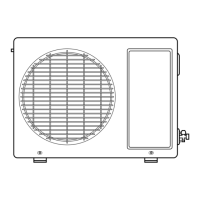
Visual diagram of outdoor cooling unit parts.
Visual diagram of outdoor heat pump unit parts.
List of part numbers for outdoor cooling components.
Part numbers for various outdoor cooling models.
Part numbers for cooling indoor CM/CN/CM models.
Part numbers for heat pump outdoor HL/EL/HL models.
Part numbers for heat pump outdoor HL/HM/HL models.
Part numbers for heat pump indoor HM/HN/HN models.
| Refrigerant | R410A |
|---|---|
| Compressor Type | Rotary |
| Power Supply | 220-240V, 50Hz |
| Weight (Indoor Unit) | 8 kg |
| Type | Split Air Conditioner |
| Heating Capacity | 7500 BTU/h |
| Operating Temperature (Cooling) | 18°C to 43°C |
| Operating Temperature (Heating) | -5°C to 24°C |