J
James SaundersAug 2, 2025
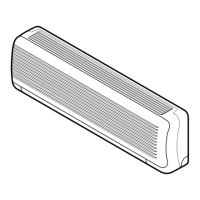
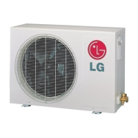
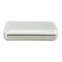
How to tell if my LG LS-S1260HL has an excessive amount of refrigerant?
- JJesse WyattAug 2, 2025
If your LG Air Conditioner has an excessive amount of refrigerant, the high pressure may not rise quickly at the beginning of operation.