51
Installation Manual
Due to our policy of continuous product innovation, some specifications may change without notification.
©LG Electronics U.S.A., Inc., Englewood Cliffs, NJ. All rights reserved. “LG” is a registered trademark of LG Corp.
MAX
MUL
TI
F
MULTI
F
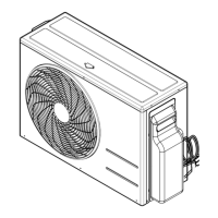
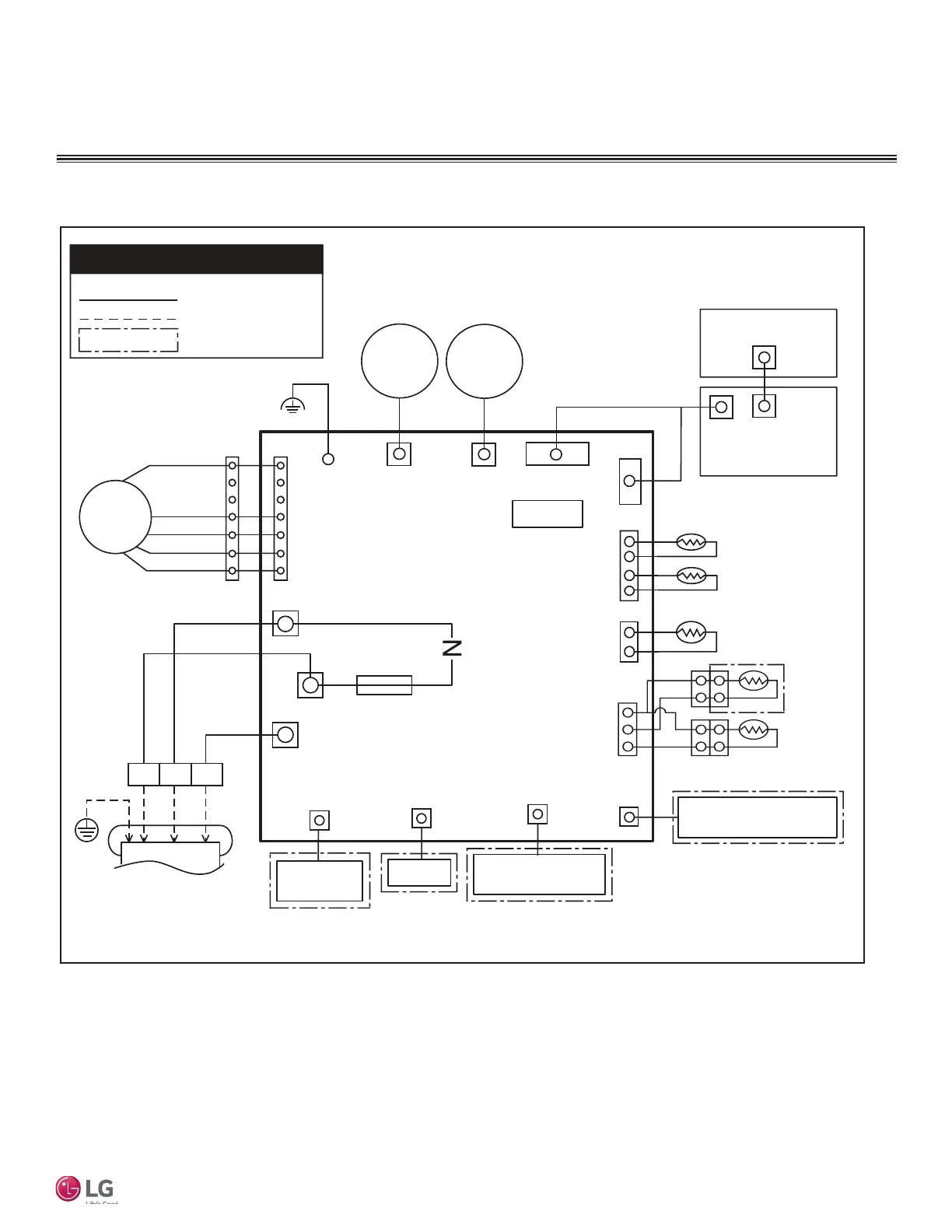
Figure 84: LSN090HSV5, LSN120HSV5, LSN181HSV5 Indoor Units Wiring Diagram.
,QGRRU8QLW(OHFWULFDO&RQQHFWLRQV
WIRING
CN_TH2
CN_TH3 CN_TH1
CN_DISP1
CN_REMO
CN_CC
CN_LINK
* This function can be optional or factory installed
depending on the application model.
Field Wiring
Factory Wiring
Optional or Factory installed*
TO OUTDOOR UNIT
CN_L1
CN_IN_N1
CN_COM2
FUSE
250V / T3.15A
MEZ64135641 Rev.01_100721
CN1
CN_MOTOR1
CN_U_D
CN_DISP3
DRY
CONTACT
AUXILIARY HEATER
RELAY KIT
THERMISTOR
(AIR + INLET PIPE)
THERMISTOR
(MIDDLE PIPE)
BK
CN_L_R
USE COPPER CONDUCTORS ONLY
MAIN
PCB ASM
11/22
Wi-Fi
WIRED REMOTE
CONTROLLER
THERMISTOR
(WATER DETECT)
THERMISTOR
(OUTLET PIPE)
CN_SUB
EEPROM
You need to buy a dedicated circuit separately.
.
INFORMATION
BK
RD
WH
BL
YL
FAN
MOTOR
STEP
MOTOR
STEP
MOTOR
FORCE S/W
DISPLAY
PWB ASM
BL
RD
BR
32(L2)1(L1)
 Loading...