54
Single Zone Mega and Mega 115V Wall Mounted Installation Manual
Due to our policy of continuous product innovation, some specifications may change without notification.
©LG Electronics U.S.A., Inc., Englewood Cliffs, NJ. All rights reserved. “LG” is a registered trademark of LG Corp.
ELECTRICAL SYSTEM INSTALLATION
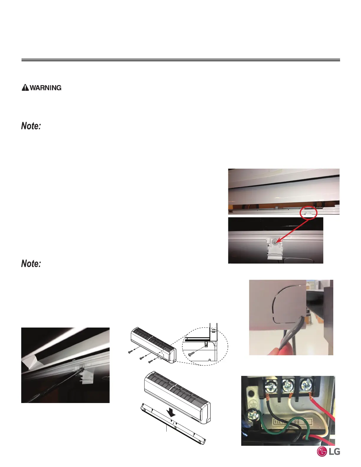
Connecting Indoor Unit Electrical Wiring (HXV Only)
• Verify that main power to the unit is completely off before proceeding with these steps as there is a risk of electrical shock, bodily injury, and /
or death.
• Follow all safety and warning information outlined at the beginning and throughout this manual. Failure to do so will cause electrical shock,
bodily injury, and / or death.
• Follow all safety and warning information outlined at the beginning and throughout this manual. Failure to do so will cause unit failure.
• Connect the communication / connection (power) cable to the indoor unit by matching the terminals on the outdoor unit control board. Verify
the color of the wires at the outdoor unit, along with the terminal numbers, match those for the indoor unit.
• Images are representative; actual appearance will vary.
• Refer to the circuit diagram on the indoor unit.
1. On the bottom cover of the indoor unit, unsnap the latches that hide the screws.
Normally, there are three (3) screws on the panel, however, models may differ.
2. Using a Phillips head screwdriver, remove the screws from the bottom cover of the
indoor unit and set aside.
3. Remove the bottom cover to access the terminal block situated at the bottom of most
indoor units.
The power wiring / communications (connection) cable is usually routed through the back /
bottom of the indoor unit (through a knockout panel).
4. Using a JIS screwdriver, connect the cable terminals to the terminal block. Ensure
wire color and terminal number of the indoor unit matches those of the outdoor unit.
Refer to the wiring diagram on the indoor unit.
Figure 96: Latch over Screws on Bottom Cover,
Indoor Unit.
Figure 97: Remove Screws from Bottom
Cover.
Figure 98: Removing the Cover from the Indoor
Unit.
Figure 99: Indoor Unit Knockout (Com-
munication Wires).
Indoor Unit Electrical Connections
Cover
Figure 100: Indoor Unit Terminal Block with
Ground Wire (Example Only).
 Loading...