55
Electrical System Installation
Due to our policy of continuous product innovation, some specifications may change without notification.
©LG Electronics U.S.A., Inc., Englewood Cliffs, NJ. All rights reserved. “LG” is a registered trademark of LG Corp.
ELECTRICAL SYSTEM INSTALLATION
Indoor Unit Electrical Connections
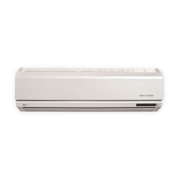
Figure 101: Terminal Block Connections for Mega 115V
090HXV, 120HXV Indoor Units.
Terminal Block
Terminal Block
Expanded View
Grounding
Cable
Connecting Cables
Cable Restrainer
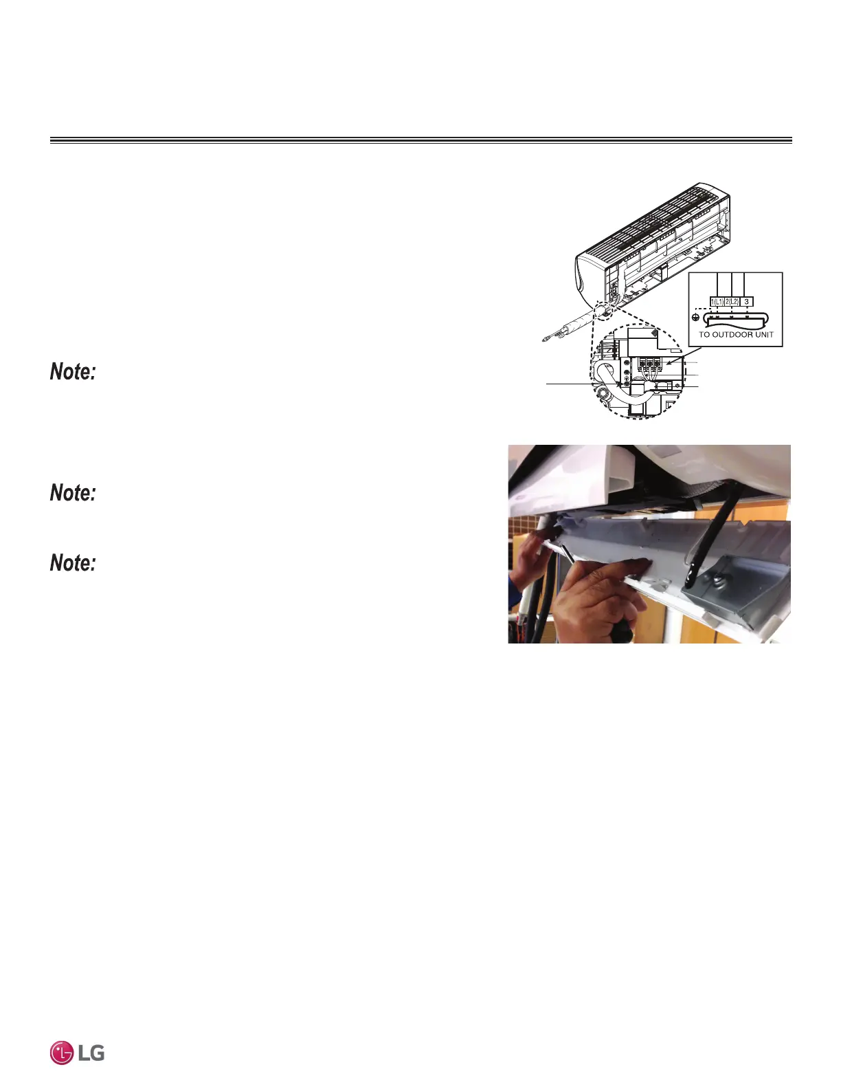
Figure 102: Reattaching the Bottom Cover.
Connecting Indoor Unit Electrical Wiring (HXV Only), continued.
5. When done, reattach the bottom cover to the indoor unit, being careful to align
cover using the rear tabs. Tap the cover gently with the palm of a hand to
ensure it engages at the bottom.
6. Using a Phillips screwdriver, securely reattach the screws to the bottom cover.
7. After the screws are in place, re-snap the latches over the screws.
• Each wire must be securely attached to the terminal block.
• Ground cable must be longer than the other wires.
• Secure the cable onto the control board using a cable tie.
• Use a conduit to protect the cable / refrigerant piping from the indoor unit to the
outdoor unit.
Position the drain hose at the bottom. Positioning the drain hose at the top of the bundle
FDQFDXVHFRQGHQVDWHWRRYHUÀRZIURPWKHGUDLQSDQLQWKHLQVLGHRIWKHLQGRRUXQLW
For more information on conduits or the bundling method, see the Refrigerant Piping
Connection section.
 Loading...