EasyManua.ls Logo

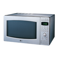
LG MC-766YS User Manual

LG MC-766YS
36 pages
To Next Page IconTo Next Page
Page #1 background imageLoading...
Page #1 background image
MICROWAVE OVEN
SERVICE MANUAL
MODEL: MC-766YS
CAUTION
BEFORE SERVICING THE UNIT, READ THE SAFETY PRECAUTIONS IN THIS MANUAL.
Website: http://biz.lgservice.com
P/NO : 3828W5S3953
August, 2004
Printed in Korea

Questions and Answers:

LG MC-766YS Specifications

General IconGeneral
BrandLG
ModelMC-766YS
CategoryMicrowave Oven
LanguageEnglish

Summary

SAFETY PRECAUTIONS

PRECAUTIONS TO BE OBSERVED BEFORE AND DURING SERVICING TO AVOID POSSIBLE EXPOSURE TO EXCESSIVE MICROWAVE ENERGY

Detailed precautions for safe servicing to prevent microwave energy exposure.

CAUTION MICROWAVE RADIATION

Warning about not exposing oneself to radiation from the microwave generator.

SPECIFICATIONS

MODEL MC-766YS

Identifies the specific LG Microwave Oven model.

Power Specifications

Details electrical power needs and output capabilities.

Component Details

Lists specs for magnetron, timer, dimensions, and weight.

Controls and Accessories

Describes cooking controls and included accessories.

Nameplate Location

Indicates the position of the oven's nameplate.

CAUTIONS

High Voltage Hazards

Highlights the dangerous nature of microwave oven components during repair.

Microwave Radiation Precautions

Precautions to avoid exposure to microwave radiation.

Servicing by Qualified Personnel

Emphasizes that only qualified personnel should service the unit.

INSTALLATIONS

Installation Guide

Step-by-step guide for setting up the microwave oven.

Grounding and Safety Advice

Instructions for proper grounding and placement safety.

OPERATING INSTRUCTIONS

Oven Feature Identification

Identifies the main external parts of the microwave.

Control Panel Layout and Functions

Explains the purpose of each button and display on the control panel.

OPERATING SEQUENCE

Clock Setting and Basic Cooking

Procedures for setting the clock and basic microwave cooking.

Advanced Cooking Modes

Instructions for multi-stage, grill, and convection cooking.

Combination Cooking and Defrost

Guidance on combined cooking and auto defrost functions.

Specialized Cooking Functions

Procedures for auto roast, auto cook, and quick start functions.

Child Lock and Time Adjustments

How to use child lock and adjust cooking time.

SCHEMATIC DIAGRAM

Power Input and Switching Circuitry

Section of the diagram showing power entry and primary switch.

Heating Elements and Transformers

Illustrates grill, convection heaters, and transformers.

High Voltage Circuit Components

Diagram of high voltage transformer, capacitor, diode, and magnetron.

Control and Monitoring Circuitry

Shows PCB, thermistor, and various switches.

CIRCUIT DESCRIPTION

General Circuitry Overview

Explains the role of the low voltage transformer and initial switch states.

Cooking Mode Control Logic

Describes how power levels and time are set and managed.

Door Interlock and Safety Circuits

Details circuit behavior when the door is opened or closed during operation.

Function-Specific Circuitry

Explains circuits for grill cooking start and power level variations.

SERVICE INFORMATION

Service Tools and Instruments

Lists essential tools and equipment for microwave servicing.

Microwave Leakage Test Procedures

Cautions and methods for checking microwave leakage.

Energy Leakage Measurement

Specific steps for conducting microwave energy leakage measurements.

MEASUREMENT WITH OUTER CASE REMOVED

High Voltage Safety Warning

Critical warning about avoiding contact with high voltage parts.

Measurement Best Practices

Notes and tips for accurate leakage measurements.

Record Keeping and Reporting

Guidelines for documenting and reporting measurement results.

MEASUREMENT OF MICROWAVE POWER OUTPUT

Microwave Power Output Measurement

Procedure for measuring microwave power using water load.

Disassembly and Adjustment Overview

Introduction to the disassembly process for adjustments.

Key Component Removal

Steps for removing outer case, power cord, and control panel.

DOOR GROSS ASSEMBLY REMOVAL

Door Assembly Removal Cautions

Warnings and important points after door replacement.

Air Duct and Magnetron Removal

Steps for removing air duct and magnetron components.

High Voltage Transformer Removal

Procedure for removing the high voltage transformer.

FAN MOTOR ASSEMBLY REMOVAL

HV Capacitor and Diode Removal

Steps for removing high voltage capacitor and diode.

Turntable Motor Removal

Procedure for removing the turntable motor.

C-MOTOR, THERMISTOR AND SHEATH HEATER REMOVAL

PCB Assembly Removal

Steps to remove the main PCB assembly.

Interlock System Installation and Adjustment

Details on interlock mechanism and switch mounting/adjustment.

INTERLOCK CONTINUITY TEST

Replacement Parts Warning

Warning to use only identical replacement parts for safety.

Interlock Switch Continuity Tests

Procedures to test the continuity of all interlock switches.

COMPONENT TEST PROCEDURE

Component Test Safety Precautions

Essential safety warnings before performing component tests.

HV Transformer and Magnetron Tests

Test procedures and expected results for HV transformer and magnetron.

COMPONENT TEST PROCEDURE (Continued)

HV Capacitor and Diode Tests

Test procedures and expected results for HV capacitor and diode.

COMPONENT TEST PROCEDURE (Continued)

Fuse, Heater, and Thermostat Tests

Test procedures for fuse, heater, and magnetron thermostat.

COMPONENT TEST PROCEDURE (Continued)

PCB Relays and Motor Tests

Test procedures for PCB relays, fan motor, and turntable motor.

COMPONENT TEST PROCEDURE (Continued)

Motor, PCB Relays, and Key PCB Tests

Test procedures for circulation motor, PCB relays, and key PCB.

TROUBLE SHOOTING

Troubleshooting General Cautions

Important safety and preliminary checks before troubleshooting.

Troubleshooting Common Problems

Steps for resolving issues like no power, low power, sparks, and uneven cooking.

TROUBLE SHOOTING (Continued)

Control Circuit Visual Faults

Identifies visual cues indicating defective control circuits.

Control Input and Display Issues

Troubleshooting for programming and display errors.

TROUBLE SHOOTING (Continued)

Oven Unresponsive and Fuse Issues

Diagnosing complete oven failure and fuse issues.

TROUBLE SHOOTING (Continued)

Cooking Start and Component Failures

Troubleshooting for failure to start cooking and non-operational components.

Low Heat Output Diagnosis

Steps to diagnose and resolve low heat production issues.

TROUBLE SHOOTING (Continued)

No Microwave Oscillation Faults

Diagnosing and resolving issues with no microwave oscillation.

TROUBLE SHOOTING (Continued)

Power Level Cooking Problems

Troubleshooting improper cooking at set power levels.

Grill Function Issues

Diagnosing and resolving problems with the grill function.

EXPLODED VIEW

Exploded View Introduction

Introduction to the section showing disassembled parts.

Exploded View of Component Groups

Shows exploded views of door, control panel, cavity, and other parts.

Related product manuals