3. Installation of outdoor unit
63 _ Heat pump 50Hz/R410A
Part 3 Design and installation
⑤
Branch pipe connection (BD unit ÷ indoor unit)
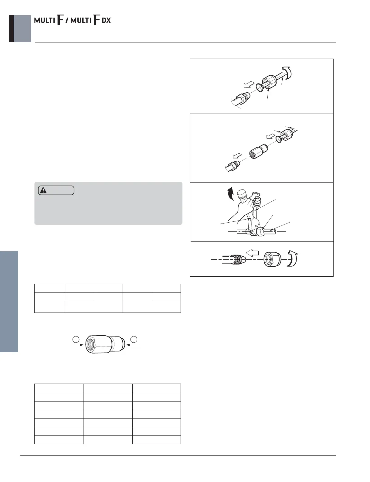
a) While piping installation you must use the connector.
• PMBD36** BD Unit
b) Align the center of the pipings and sufficiently tighten the
flare nut by hand
*Connecting pipe size
Indoor Units Gas Liquid
18k, 24k
ⓐⓑⓐⓑ
Ø9.52(3/8)’Ø12.7(1/2) Not necessary
Indoor Units Gas side Liquid side
5k Ø9.52(3/8) Ø6.35(1/4)
7k Ø9.52(3/8) Ø6.35(1/4)
9k Ø9.52(3/8) Ø6.35(1/4)
12k Ø9.52(3/8) Ø6.35(1/4)
18k Ø12.7(1/2) Ø6.35(1/4)
24k Ø12.7(1/2) Ø6.35(1/4)
[Connector]
a
b
[Unit : mm(inch)]
[Unit : mm(inch)]
a) Align the center of the pipings and sufficiently tight-
en the flare nut by hand.
b) Tighten the flare nut with a wrench.
c) Wrap the insulation material around the connect-
ing portion.
① Overlap the Refrigarant cable insulation material and the
indoor unit pipe insulation material. Bind them together
with vinyl tape so that there is no gap.
② Wrap the area which accommodates the rear piping
housing section with vinyl tape.
③ Align the center of the piping and sufficiently tighten the
brass cap by hand.
④ Tighten the brass cap with a wrench.
⑤ Wrap the joint part with insulation.
Flare nut
Pipes
CASE. 1
BD Unit side flare
BD Unit side flare
Indoor unit side flare
Indoor unit side flare
Ø 9.52(7k/9k/12k Btu/h)
Connecting socket
Flare nut
Pipes
CASE. 2
Ø 9.52
Ø12.7(18k/24k Btu/h)
Ø 9.52
Spanner (fixed)
Connection pipe
Flare nut
Torque
wrench
• Never use the plastic cap for sealing.
• Make sure to use brass cap with the end of pipe sealed or
welded tightly.
CAUTION
 Loading...