15
Installation Manual
Due to our policy of continuous product innovation, some specifications may change without notification.
©LG Electronics U.S.A., Inc., Englewood Cliffs, NJ. All rights reserved. “LG” is a registered trademark of LG Corp.
MA
TI
F
TI
GENERAL DATA
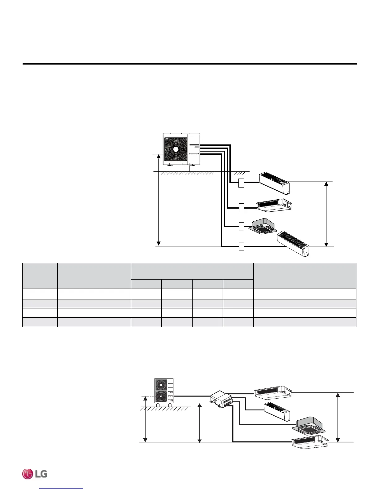
Typical Multi F/Multi F Max Systems
Max. 49.2 feet
Max. 24.6 feet
A
B
C
D
Typical Multi F System
Example: LMU36CHV outdoor unit with four (4)
indoor units connected.
ODU: Outdoor Unit.
IDU: Indoor Unit.
A, B, C, D: Piping from Outdoor Unit to Indoor Unit.
Major System Components
A typical Multi F system consists of an outdoor unit (ODU), refrigerant piping, and two (2) to four (4) indoor units (IDUs). The Art Cool Mirror
wall-mounted units described in this manual are one of the types of IDUs that can be connected to a Multi F system.
A typical Multi F Max system consists of an ODU, refrigerant piping, one or two branch distribution units (BDU), and two (2) to eight (8) IDUs.
The Art Cool Mirror wall-mounted units described in this manual are one of the types of IDUs that can be connected to a Multi F Max system.
Example: LMU540HV outdoor unit with four
(4) indoor units, and one (1) branch distribu-
tion unit connected.
ODU: Outdoor Unit.
IDU: Indoor Unit.
BDU: Branch Distribution Unit.
A: Main Piping.
B: Branch Piping (Branch Distribution Unit to
Indoor Unit[s]).
A
h2 ≤ 49.2 feet
h3 ≤ 32.8 feet
h1 ≤ 98.4 feet
BDU
IDU
IDU
IDU
IDU
B
B
B
B
Typical Multi F MAX System with One Branch Distribution Unit
Outdoor
Unit
Minimum Length for Each
Pipe Segment (ft.)
Maximum Equivalent Pipe Length
to Each Indoor Unit (ft.)
Maximum Equivalent Pipe Length
for Each System (ft.)
A B C D
LMU18CHV 10 82 82 - - 164
LMU24CHV 10 82 82 82 - 246.1
LMU30CHV 10 82 82 82 82 246.1
LMU36CHV 10 82 82 82 82 246.1
Table 6: Multi F Outdoor Unit Refrigerant Piping System Limitations.

 Loading...