74
MULTI F / MULTI F MAX Outdoor Unit Installation Manual
Due to our policy of continuous product innovation, some specifications may change without notification.
©LG Electronics U.S.A., Inc., Englewood Cliffs, NJ. All rights reserved. “LG” is a registered trademark of LG Corp.
MULTI
F
MAX
MULTI
F
Between Multiple Indoor Units Operating as a
Group (Group Control)
If any indoor units were specified to operate in unison:
• Before running cable, decide which indoor unit will be the “Main.” The other indoor
units in that group will be designated as “Sub(s).” The zone controller will be connected
to the “Main.”
• Set the pertinent DIP switch at each indoor unit to identify the Main and Sub(s). On wall
mounted indoor unit models, set the assignment using the handheld remote controller.
• Use a daisy chain configuration and connect all of the group’s indoor units together
starting at the “Main” unit.
•
NEVER splice, cut, or extend cable length with field provided cable. Always
include enough cable to cover distance between all components.
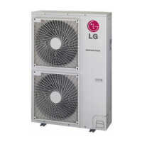
For indoor units with hardwired connections SIG - 12V - GND (Comm.)
terminals:
• From the controller to the main indoor unit, use 22 AWG, 3-conductor, twisted, strand-
ed, unshielded. All wiring must comply with all applicable local / national codes.
• From the main indoor unit to the sub indoor unit(s), daisy chain using 22 AWG, 3-con-
ductor, twisted, stranded, unshielded. All wiring must comply with all applicable local /
national codes.
•(
Do not attach wire to 12VDC terminal to the sub indoor units). All wiring must
comply with all applicable local and national codes.
• NEVER splice, cut, or extend cable length; always include enough cable to cover
distance between all components.
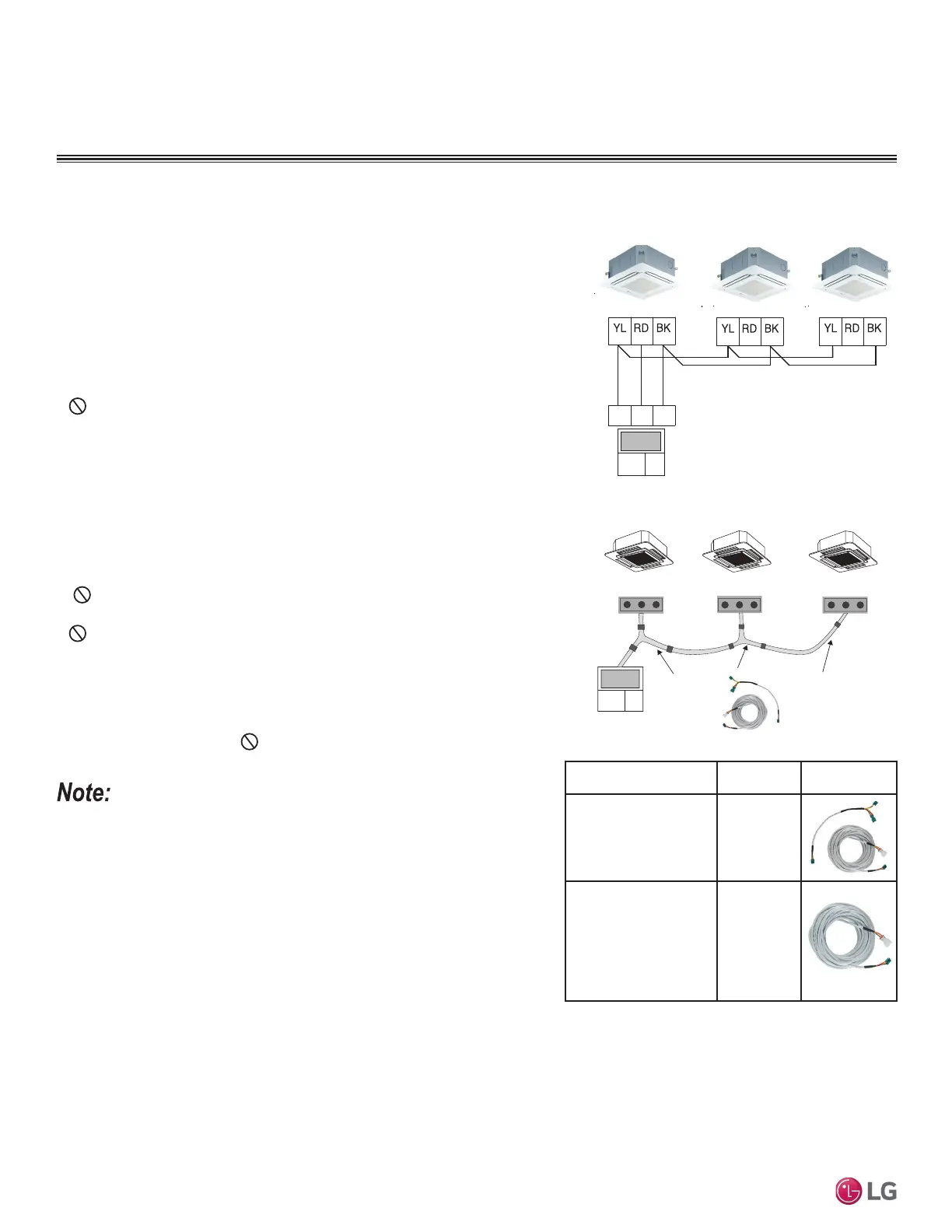
For indoor units with CN-REMO connections:
8VHRQHRUPXOWLSOH*URXS&RQWURO.LWVVROGVHSDUDWHO\FRQWDLQLQJH[WHQVLRQDQG
Y-splitter cables. Use one (1) group control cable kit for each indoor unit in the group
except for the last indoor unit. NEVER splice, cut, or extend cable length with
field provided cable.
• Cable connected to zone controller is the factory default connection.
• Indoor unit connections depend on indoor unit type.
Figure 98: Example of Indoor Unit Group to Zone
Controller Connections (Sig-12V-GND [Comm.]
Terminal).
Figure 99: Example of Indoor Unit Group to Zone
Controller Connections (CN-REMO).
Main Indoor Unit
Indoor Unit
Indoor Unit
Signal
12VDC Comm.
Signal
12VDC Comm.
45
6
Signal
12VDC Comm.
Signal
12VDC Comm.
CN-REMO
On All Indoor Unit Styles
CN-REMO
On All Indoor Unit Styles
CN-REMO
On All Indoor Unit Styles
LG
Supplied
LG Supplied Group Control Kit (PZCWRCG3)
Accessory
Model
Number
Image
Wired Remote Group
Control Cable Assembly,
Required for connecting
multiple indoor units to a
control group
PZCWRCG3
Wired Remote/Wired
Remote Extension Cable,
Required for extending
the distance between
indoor units or remote
controllers in a control
group
PZCWRC1
Table 33: Accessories for Some Group Control Applications.
General Specifications
• Wired remote controllers can be connected to all indoor unit types.
• Wireless controllers can be used in conjunction with wired remote controllers.
• A dry contact unit can be connected with a central controller simultaneously.
- The main indoor unit is recognized by the dry contact unit and the central controller.
- Group Control only available for indoor units manufactured after February 2009.
- The central controller can control indoor units after setting the address of the
main indoor unit only.
- Sub indoor unit cannot be individually controlled by central controller.
- Sub indoor unit will operate like the main indoor unit.
• If an error occurs with the indoor unit, the error will be displayed on the wired remote controller.
• The following functions are available with group control:
• Selection of operation options (operation/mode/set temperature)
• Control of air flow rate (High/Medium/Low)
ELECTRICAL
,QVWDOODWLRQ

 Loading...