59
Wiring
Due to our policy of continuous product innovation, some specifications may change without notification.
©LG Electronics U.S.A., Inc., Englewood Cliffs, NJ. All rights reserved. “LG” is a registered trademark of LG Corp.
MULTI
F
MAX
MULTI
F
PI485
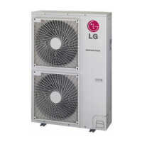
PI485 V-net Control Integration Board for Outdoor Units adapt Multi F, Multi F MAX systems to a LG VRF
system central protocol for integration with LG central controllers. The PI485 is installed in the Multi F /
Multi F MAX outdoor unit. For more information on PI485 installation, see the PI485 installation manual.
Figure 81: PI485 Board (Appear-
ance may differ depending on
model).
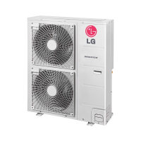
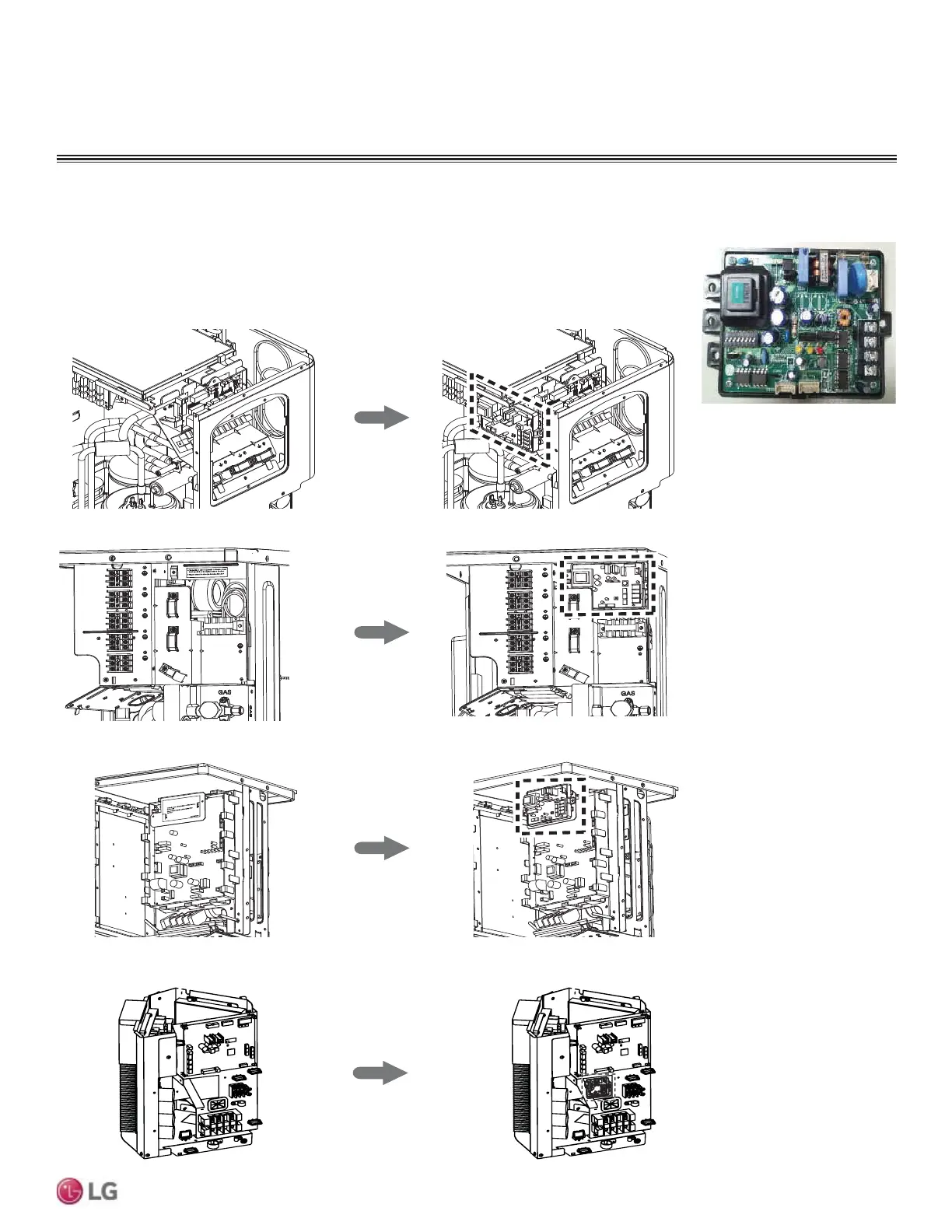
WIRING
Power Wiring and Communications Cable Connections
Multi F LMU18CHV, LMU24CHV
Multi F LMU30CHV, LMU36CHV
T
hi
s
la
b
e
l
is
s
h
o
u
ld
be app
li
ed
in
th
e
l
o
c
a
ti
o
n
w
h
e
re
L
GA P(Sub PCB
f
o
r C en
t
r
a
l
Co
n
t
r
o
ll
e
r
i
s
ins
t
a
lle
d
.
Ple
as
e
co
n
n
e
c
t
t
h
e
w
i
r
e
a
f
t
er in
s
t
a
l
lin
g
t
h
e
L
GA
P
.
T
his
i
s
th
e
s
p
a
c
e
f
o
r
in
s
t
a
l
l
a
ti
o
n
o
f
PI
4
8
5
G
a
te
w
a
y.
(Ac
c
e
ss
o
ry
)
Pl
e
a
s
e
c
o
n
n
e
c
t
t
h
e
w
i
r
e
a
fte
r
i
ns
ta
ll
i
ng
PI
4
8
5
G
a
tew
a
y.
Screw Hole
Screw Hole
MEZ30
1
71
8
0
2
Multi F MAX LMU480HV, LMU540HV
Multi F MAX LMU600HV
Figure 82: PI485 Installation Area in Multi F and Multi F MAX Outdoor Units.
 Loading...