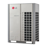
Do you have a question about the LG Multi V 5 ARUM160LTE5 and is the answer not in the manual?
Information on serious injury, death, or product damage if directions are ignored.
Hazards from unqualified persons, manual use by technicians, proper wiring, grounding, and contacting dealers.
Warnings against self-installation, flammables, incorrect breakers, improper stands, and incorrect gas usage.
Warnings against unspecified power cords, dedicated outlets, and preventing water entry.
Precautions on touching switches, sharp edges, outdoor unit access, and inlet grilles.
Checks for refrigerant leaks, noise, level installation, combustible gas, and cable selection.
Warnings against special environments, blocking inlet/outlet, secure connections, and proper transportation.
Sequence of installation tasks from preparation to customer transfer.
Details on allowable indoor/outdoor unit combinations.
Information on R410A refrigerant properties and handling.
Guidelines for selecting an optimal installation space.
Avoiding corrosive environments, heavy snowfall, and noise disturbance.
Specific location requirements for HR units.
Specifies minimum clearances for various installation configurations.
Measures for winter operation, snow protection, and wind direction.
Guidelines for carrying and lifting the unit securely.
Precautions during carrying, avoiding damage, and proper lifting.
Requirements for fixing the unit securely with bolts and using anti-vibration materials.
Risks of unit dropping due to insufficient support strength.
Steps for cutting pipes, removing burrs, and performing flaring.
Using charge hoses, checking leaks, and using proper torque.
Procedures for opening and closing shutoff valves.
Flare nut tightening torque and shutoff valve insulation.
Requirements for pipe thickness, purity, and handling.
Key principles of drying, cleanliness, and airtightness for piping.
Warnings about using nitrogen, pressure valves, and antioxidants.
Details for HP system installation and valve operation.
Warnings about leaks during welding, poisonous gas, and closed spaces.
Diagrams for connecting multiple outdoor units.
Using approved materials, cleaning, and reducing bends.
Observing rated length, height difference, and diameter restrictions.
Warnings on recharging refrigerant, mixing refrigerants, and pipe diameter selection.
Precautions and connection details for HR systems.
Warnings about leaks during welding, poisonous gas, and closed spaces.
Steps for hanging bolts, installing nuts, and ensuring level installation.
Connecting liquid, low pressure gas, and high pressure gas pipes.
Classifying HR units and installing zoning control.
Warnings on branch pipe capacity, total capacity, and zoning functions.
Using approved materials and complying with wall thickness regulations.
Cleaning, preventing contaminants, reducing bends, and observing piping restrictions.
Warnings on recharging refrigerant, mixing refrigerants, and pipe diameter selection.
Options for front or side pipe connections.
Steps to remove the leakage prevention cap before pipe work.
Method for drawing out pipes on the front side.
Avoiding damage during knock-out work and removing burrs.
Method for drawing out pipes on the bottom side.
Diagrams illustrating Y branch, combination, and header methods.
Method for drawing out pipes on the front side for HR systems.
Steps to remove the leakage prevention cap before pipe work.
Illustrating connection for 4 outdoor units.
Table specifying pipe diameters based on total capacity.
Formula and limits for total pipe length.
Conditions for applying longer pipe lengths.
Pipe diameter requirements for indoor unit connections.
Table detailing pipe diameters based on ODU capacity.
Warning about increasing pipe diameter B if it's larger than main pipe A.
Illustrating various connection patterns.
Diagram and parameters for connecting outdoor to indoor units.
Tables detailing pipe length limits for different connection methods.
Warnings about increasing pipe diameter for length/level differences.
Table detailing pipe diameters based on ODU capacity.
Warning about increasing pipe diameter B if it's larger than main pipe A.
Table specifying pipe diameters based on total capacity.
Conditions for applying longer pipe lengths.
Pipe diameter requirements for indoor unit connections.
Illustrating general pipe connections between outdoor units.
Application of oil traps for longer pipe lengths and specific conditions.
Illustrating incorrect pipe connections and oil accumulation.
Details on Y branch fittings and installation.
Details on header fittings and installation.
Specifications for header units.
Specifications for Y branch pipe units.
Illustrating horizontal, vertical, and other distribution methods.
Function for creating vacuum, setting methods, and turning off.
Warning about ODU operation stopping during vacuum mode.
Procedure for pressurizing nitrogen gas, checking leaks, and temperature correction.
Preventing nitrogen entry and proper cylinder positioning.
Vacuum drying procedure, moisture, and leak warnings.
Warnings against using air/oxygen and the risks of fire/explosion.
Manifold gauge and handle connections for HP systems.
Diagrams for refrigerant charging in HR systems.
Warnings about vacuuming, refrigerant amount, and potential issues.
Formula and tables for calculating additional refrigerant.
Requirements for insulating refrigerant piping to prevent condensation.
Cautions and examples of correct and incorrect insulation practices.
Regulation for refrigerant leakage and equation for safety.
Diagrams and materials for wall, floor, and roof penetrations.
Diagrams showing master/slave outdoor and indoor unit connections.
Following government regulations for electrical work.
Risks of electric shock or fire from improper electrical work.
Grounding outdoor units and providing wiring allowance.
Using round terminals, avoiding mixed thickness wires, and securing cables.
Removing panels and connecting communication cables.
Specifications for communication and remote control cables.
Grounding shielded wires.
Recommended spacing between communication and power cables.
Ensuring proper earthing to prevent electric shock.
Separate power supplies, voltage drops, cable size, and cord types.
Earth leakage breaker requirements and correct breaker/fuse usage.
Compliance with EN/IEC standards for voltage and harmonic currents.
Diagrams for field wiring of single outdoor units.
Requirements for preventing electric shock and noise.
Installing a main switch and phase protection circuits.
BUS and STAR type communication cable connections.
Warnings about total capacity limits for series wiring.
Illustrating wiring connections for UXA model.
Avoiding interference with the oil level sensor.
Checking settings via DIP switch and 7-segment LED.
Settings for HR unit board and switch functions.
DIP switch settings for master and slave units.
Selecting between auto and manual valve addressing.
Setting up zoning control for indoor units.
DIP switch settings for different HR unit models and branch connections.
Using the rotary switch for HR unit addressing.
Using DIP and tact switches for manual valve addressing.
Normal manual valve addressing and addressing with zoning.
Steps for performing automatic addressing of indoor units.
Cautions regarding PCB replacement, power supply, timing, and DIP switch settings.
Steps for automatic pipe detection.
Warnings and cautions for pipe detection processes.
Steps for manual pipe detection.
Flowchart illustrating the auto pipe detection process.
Examples of manual valve addressing for zoning and non-zoning.
Flowchart for manual addressing of pipe detection.
Steps to check pipe detection results.
Setting the master indoor unit in zoning.
Example of checking valve addresses.
Setting group numbers for indoor units.
Warnings on matching valve address and central control address.
Selecting optional functions.
Overview of optional mode selection.
Table detailing function settings and modes.
Cautions regarding performing optional functions.
Mode to secure airflow rate under static pressure.
Table showing maximum fan RPM for different steps.
Function to reduce fan noise at night.
Setting for overall defrost operation.
Method for setting the outdoor unit address.
Adjusting airflow for IDU heating based on capacity.
Setting for snow removal and rapid defrost.
Setting for low ambient kit.
Adjusting target low pressure based on ODU temperature.
Function to remove dust using reverse run fan.
Setting the maximum compressor frequency limit.
Setting limits for maximum fan RPM.
Function for setting variable target pressure.
Setting humidity reference.
Connecting central control at the indoor unit side.
Setting the compressor input current limit.
Displaying power consumption on the wired remote controller.
Operation mode for base pan heater.
Setting for overall defrost in low temperatures (heating).
Reducing ODU energy consumption without thermo-off.
How errors are indicated and displayed on units and controllers.
List of indoor unit related errors and their causes.
Table listing outdoor unit errors, titles, and causes.
Listing further outdoor unit errors, titles, and causes.
Errors related to network and HR unit communication.
Information on R410A refrigerant and concentration limits.
Actions to take when refrigerant concentration limits are exceeded.
Steps to check and calculate refrigerant concentration limits.
Method to calculate minimum room capacity.
Warnings against corrosive gases and sea wind direct exposure.
Guidelines for selecting outdoor unit location near the seaside.
Information on airborne noise levels and exposure.
| Brand | LG |
|---|---|
| Model | Multi V 5 ARUM160LTE5 |
| Category | Air Conditioner |
| Language | English |


 Loading...