38
Multi V Ducted Indoor Units
Due to our policy of continuous product innovation, some specifications may change without notification.
©LG Electronics U.S.A., Inc., Englewood Cliffs, NJ. All rights reserved. “LG” is a registered trademark of LG Corp.
GENERAL INSTALLATION GUIDELINES
Maintenance Clearances
Chassis Code
Control Panel Access Major Maintenance Access
Location* C1 C2 C3 Location A1 A2 A3*
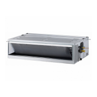
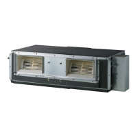
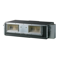
High-Static Ducted Indoor Units
BH Right End 12 12 10-1/2 Bottom 35 18 11
BG Right End 12 14 12 Bottom 47 18 12
BR Right End 12 14 15 Bottom 49 24 15
B8 Right End 12 14 18 Bottom 62 28 19
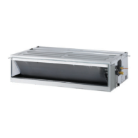
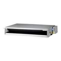
Low-Static Ducted Indoor Units
L1 Right End 10 12 8 Bottom 30 25 8
L2 Right End 10 12 8 Bottom 38 25 8
L3 Right End 10 12 8 Bottom 46 25 8
Low-Static Built-In Ducted Indoor Units
B3 Left End 10 12 8 Bottom 34 23 8
B4 Left End 10 12 8 Bottom 44 23 8
Table 16: Minimum Maintenance Clearances (in.).
C3
C2
A1
A3
A2
Figure 15: High-Static Ducted (BG/BR/B8/BH) Indoor Unit
Maintenance Clearances.
Figure 16: Low-Static Ducted (L1/L2/L3) Indoor Unit
Maintenance Clearances.
Figure 17: Low-Static Built-In Ducted (B3, B4) Indoor Unit
Maintenance Clearances.
Note:
When space is available, best practice would be to
leave two (2) to three (3) inches on the end opposite the
control panel. Leave adequate room for visual inspection,
pipe installation, brazing, power wiring, control wiring,
and pipe insulating activities. Provide adequate access to
service nearby piping, drain lines, shutoff valves, etc., fol-
lowing the dimension guidelines listed in the table below.
*Does not apply when the ceiling surface below can be removed.
A1
A2
A3
C2
C1
C3
 Loading...