59
Installation Manual
Due to our policy of continuous product innovation, some specifications may change without notification.
©LG Electronics U.S.A., Inc., Englewood Cliffs, NJ. All rights reserved. “LG” is a registered trademark of LG Corp.
Indoor Unit Terminal Block
L(L1) N(L2)
A------ABB
GND 12V
DRY2DRY1
INTERNETIDUSODU
Outdoor Unit Terminal Block
Power Input
208-230V /
60 Hz / 1 Phase
Ground
YL RD
A B
BK
Wired Controller
Indoor Unit Terminal Block
L(L1) N(L2)
A------ABB
GND 12V
DRY2DRY1
INTERNETIDUSODU
Outdoor Unit Terminal Block
Power Input
208-230V /
60 Hz / 1 Phase
3(A) 4(B)
Ground
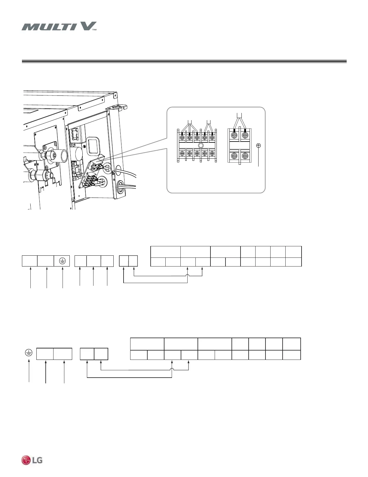
WIRING
Indoor Unit Communication Cable Connections
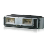
Figure 63: Location of Power Wiring and Communications Cable Terminals in the Mid Static (M2/M3) and High Static (M2/M3) Ducted Indoor Units.
Figure 64: Terminal Block in the High Static (B8/M2/M3) and Mid Static (MA/M2/M3) Ducted Indoor Units.
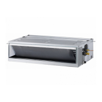
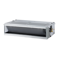
Figure 65: Terminal Block in the Low Static (L1, L2, L3 Chassis) Ducted Indoor Units
Power
Supply
(208/230V)
ODU
Comm
Wired
Remote
Controller
YL RD BK
L(L1) N(L2)
GN/YL
A B
 Loading...